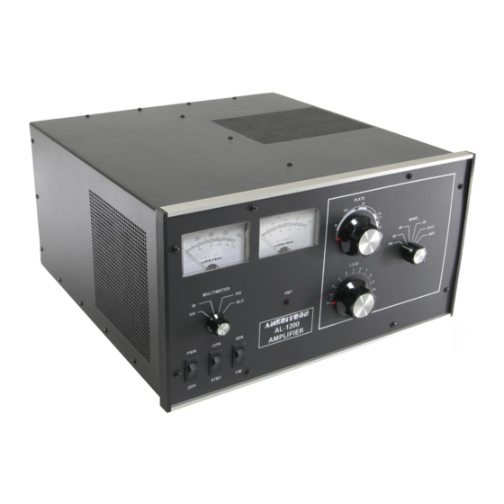
AMERITRON AL-1200 Gebrauchsanweisung - Seite 11
Blättern Sie online oder laden Sie pdf Gebrauchsanweisung für Verstärken AMERITRON AL-1200 herunter. AMERITRON AL-1200 15 Seiten. Full power linear amplifier

ALC (Automatic Level Control)
The primary use of the ALC is to reduce the input drive power
to a safe level for the AL-1200. The maximum drive of the AL-
1200 will tolerate is approximately 130 watts. At this drive level
the output of the AL-1200 may be in excess of 2000 watts when
properly tuned. The ALC should be connected and adjusted
after the amplifier is properly tuned on CW. Use a shielded
audio-type cable with a standard male phono connector to
connect the 0-20 volt negative ALC voltage to the exciter ALC
input. Consult the exciter manual for proper connection details.
Setting the ALC ADJ Control
Proper adjustment of the rear panel ALC control can be
achieved by the following steps:
1. Load the amplifier according to the tune-up instructions (with
the ALC disconnected from the exciter) to the desired
maximum power.
2. Connect the ALC line and rotate the ALC control fully
clockwise looking at the rear of the unit.
3. Set the MULTIMETER switch to the PO position or observe
an external PEP meter or oscilloscope.
4. Set the transmitter audio control about 20% higher than
normal
5. Speak in the microphone in a normal tone of voice and
observe the reading on the 2000 RF Watts scale.
The AL-1200 will operate with full output on all WARC bands except 24.5 MHz. The
AL-1200X (export model) will operate with full output on all WARC bands.
MAKE NO ATTEMPT TO PUT THIS AMPLIFIER IN SERVICE WITH THE COVER
REMOVED! CONTACT WITH VOLTAGES INSIDE THIS AMPLIFIER CAN BE
FATAL! ALWAYS DISCONNECT THE AMPLIFIER FROM THE POWER MAINS
AND WAIT FOR THE FILTER CAPACITORS TO DISCHARGE BEFORE
REMOVING THE COVER.
6. Adjust the ALC ADJ control on the rear panel until the
The exciter internal ALC will maintain linearity. The amplifier
ALC will prevent over-power operation.
SSB PROCEDURE
Tune the Exciter and Amplifier as described in "TUNE-UP CW
1. Place the SSB-CW switch in the SSB position.
2. Adjust the exciter gain control to permit voice peaks to reach
the same value the peak output meter read on CW when
fully loaded. The plate and grid currents should remain well
below 50% of the CW values during normal modulation.
NOTE: ,
Some exciters will put out short duration high power RF pulses
when first keyed. Exciter power output peaks may reach or
exceed full output level even if the exciter's power control has
been adjusted to deliver reduced power under "keydown"
conditions.
The amplifier loading control must be set high enough
(clockwise) to prevent extremely high energy levels from
developing in the plate and grid circuits of the amplifier. DO
NOT "UNDERLOAD" THE AMPLIFIER TO REDUCE
POWER. Never "retune" the amplifier to produce higher ef-
ficiency with reduced drive. Poor linearity, splatter or even
damage to components may result from failure to follow these
i t
STANDARD FREQUENCY COVERAGE
WARNING!!!
amplifier output is no more than the desired maximum
power obtained in step 1.
ti
