DAGU Doodle Bot Handbuch - Seite 7
Blättern Sie online oder laden Sie pdf Handbuch für Robotik DAGU Doodle Bot herunter. DAGU Doodle Bot 12 Seiten.

Wiring Instructions:
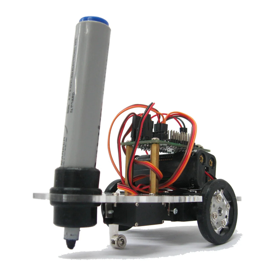
Once you have assembled the robot you need to connect the wires. Start by checking that the jumper near the
power switch is selecting 5V for power. If it is set to battery voltage then the sensor outputs might be high
enough to damage the digital inputs D2 & D3.
Connect the left and right motors as shown in the photo. Make sure the jumpers are on D7, D8, D9 & D10 so
that the processor is connected to the motor driver. Now connect the power wires from the battery. Make sure
you connect the red wire to the +positive connection.
Next we need to connect the servo and wheel encoder sensors. These all have three wires - black/brown is
the ground wire and goes to the outer edge of the PCB. The red wire is the +positive and should be in the
center. The white/orange wire is the signal wire and will be closest to the processor.
The right wheel sensor connects to D2, the left wheel sensor connects to D3 and the servo is connected to
D12.
Battery +
Battery -
Power
Switch
+V: Bat/5V
D2
D3
D4
D5
D6
D11
D12
D13
Gnd 5V
5V
S
S
D9 D7 D10 D8
D9 D7 D10 D8
motor
USB
5V G
G T
S
S
5V
5V
Gnd
T
R
R
X
X
X
X
ATmega
ATmega
8A
8A
Left
Right
motor
Reset
A5
A4
A3
A2
A1
A0
D13
LED
