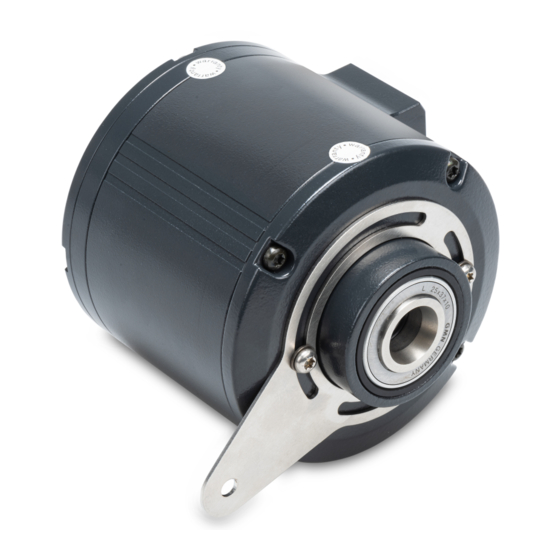
Baumer HUBNER BERLIN PROFI NET microGen HMG10P Betriebshandbuch - Seite 3
Blättern Sie online oder laden Sie pdf Betriebshandbuch für Medienkonverter Baumer HUBNER BERLIN PROFI NET microGen HMG10P herunter. Baumer HUBNER BERLIN PROFI NET microGen HMG10P 44 Seiten. Incremental encoder with magnetic sensing
Auch für Baumer HUBNER BERLIN PROFI NET microGen HMG10P: Montage- und Betriebsanleitung (32 seiten), Montage- und Betriebsanleitung (40 seiten)

Baumer Hübner
6.2.3
Switching level additional output incremental (optional) ....................................................... 29
6.2.4
Programming interface (only for programmable variant) ...................................................... 29
6.2.5
LED activity indicator ............................................................................................................ 29
6.2.6
Output switching behavior Speed switch (optional) .............................................................. 30
6.2.7
Connecting the supply cable ................................................................................................. 30
6.2.8
Pin assignment ..................................................................................................................... 32
6.3
Sensor cable....................................................................................................................................... 33
6.4
Z-PA.SDL.1 WLAN adapter: Programming device for HMG10P/PMG10P ........................................ 33
7 Disassembly................................................................................................................................................. 34
7.1
Removing the encoder from blind hollow shafts or cone shafts ......................................................... 35
7.1.1
Loosen fastening aids provided at the blind hollow shaft...................................................... 35
7.1.2
Threaded pin to secure at blind hollow shaft ........................................................................ 36
7.1.3
Detaching the encoder from blind hollow shafts ................................................................... 37
7.2
Detaching the encoder from through-hollow shaft .............................................................................. 38
8 Technical data.............................................................................................................................................. 39
8.1
Blind-hollow shaft dimensions ............................................................................................................ 40
8.2
Through hollow shaft dimensions ....................................................................................................... 41
8.3
Cone shaft dimensions ....................................................................................................................... 41
V1, T1 | HMG10 & HMG10P EtherNet/IP
Operating Manual
List of contents
iii
