AmpliVox SSB1240 Benutzerhandbuch - Seite 4
Blättern Sie online oder laden Sie pdf Benutzerhandbuch für Lautsprechersystem AmpliVox SSB1240 herunter. AmpliVox SSB1240 6 Seiten. Duo tandem line array

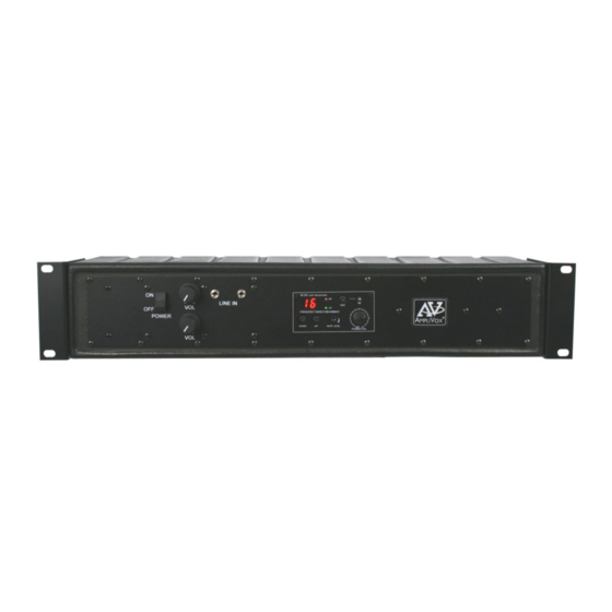
Amplifier Module
User Side
•
Line In: Two 3.5mm input connectors (1) are
provide for connecting Audio sources from com-
puters, MP3 players, phones, tablets etc.
•
Line Volume Control: Use this control (2) for
adjusting the volume output from the Audio
sources connected to the Line In connectors (1).
•
Microphone Volume Control: Use this control
(3) for adjusting Wired Microphone connected to
this input (5).
Connection Side
•
Line In: One 3.5mm input connector (4) is pro-
vide for connecting an Audio source.
•
Microphone Input: Plug in a wired microphone
(5) with either a 1/4" male connector or a 3 Pin
XLR connector.
Wireless Receiver Panel
•
Channel Display (A)
•
RF - Radio Frequency Indicator (B)
•
AF - Audio Frequency Indicator (C)
•
ASC / IR Auto Channel Select (Handheld Only) (D)
•
Select Buttons - Manual Channel Selection (E)
•
Mute Level Adjustment (F)
•
Volume Control (G)
Receiver / Transmitter Setup:
•
The wireless receiver has its own POWER / VOLUME Control
(G). Turn Power On. A Frequency Channel will appear in the
Channel Display (A). Press Select Buttons (E) to select a
channel. Channel number must match channel number on
wireless microphone transmitter.
•
The wireless microphone transmitter bodypack is operated by
1 - "AA" 1.5 Volt alkaline battery. Slide off battery cover (H)
and install battery as shown. Make certain the battery is fully
seated in its compartment so the cover slides in place easily.
Battery life with alkaline batteries is approximately 8 hours of
operating time.
•
Select a channel (1-16) on side panel (I) using the supplied
screw driver to select channel number. Channel selected
should match channel on receiver. When transmitter and
receiver are set to correct channel the RF indicator (B) will
glow red when transmitter is turned on.
•
Plug the headset microphone into the MIC Input Jack (K).
The microphone can be clipped to a necktie or other clothing,
using the supplied clip. The lapel mic should be placed under
the chin, as close to the center of the body as possible.
•
Slide the power ON/OFF switch (J) to the ON position (the
LED indicator light will illuminate green). Replace batteries
when this LED turns red. Slide this lever to the middle position
to temporary silence (MUTE) microphone.
●
RECEIVER MUTE LEVEL (F) is set at half way mark when it
leaves the factory. If speaker sound is breaking up, turn level
clockwise with small screwdriver until condition improves.
User Side
3
Connection Side
4
A
Wireless Microphone Transmitter - Bodypack
Channel Selector
4
2
1
B
C
D
E
G
F
Battery Cover
Top Panel
I
J
K
5
H
