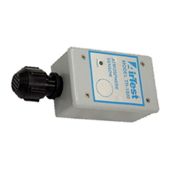
AirTest TR-1000 Handbuch für Betrieb und Wartung - Seite 4
Blättern Sie online oder laden Sie pdf Handbuch für Betrieb und Wartung für Zubehör AirTest TR-1000 herunter. AirTest TR-1000 6 Seiten. 4-20 ma sensor / transmitter, vehicle exhaust detection applications

TO CONTROLLER
10-30VDC INPUT POWER
(Shielded wire - 3x18 ga. min.)
-
READY LED
(GREEN)
LD1
V- A V+
RV1
R13
R14
ACTIVE LED
(YELLOW)
LD2
(YELLOW)
INDICATORS, TEST POINTS & POTENTIOMETERS
A. The ready, green LED, indicates that power has been correctly applied.
B. The active, yellow LED
When "ON" indicates the sensor output is in the active area.
When "OFF" indicates the sensor output is below zero or overrange.
C. Test Points are:
TP1 (Red)
TP2 (Black) 5V ±0.1v, circuit power.
TP3 (Yellow) -OUTPUT VOLTAGE, 0.4 to 2.0 volts (equates to 4-20 mA).
TP4 (White) -SIGNAL test point, typically 0.0 to 1.6 volts.
D. Potentiometers:
RV1
-ZERO potentiometer
RV2
-GAIN potentiometer
RV3
-ZERO OFFSET potentiometer
IF YOU HAVE THE 24VAC
POWER OPTION GOTO PAGE 7
+
FOR CORRECT WIRING DIAGRAM
4-20mA
OUTPUT
SENSOR WIRING
SIG
VR1
HS1
R2
R1
C2
G B W R
(WIRE COLOURS)
R3
D1
Q1
D2
Q2
D3
DP1
R9
R8
U1
C3
R12
R10
Q5
Q4
R11
C4
R15
RV2
RV3
TP3
Z1
FIG.1.
-COMMON reference point for TP2,TP3 & TP4, voltmeter
POSITIVE connection.
TP2
(BLACK)
TP1
(RED)
R6
R4
C6
R5
R21
C5
R20
R7
R22
C8
TP4
(WHITE)
C7
R16
R17
R18
R19
4
