ATX Q series Handbuch für Installation und Betrieb - Seite 6
Blättern Sie online oder laden Sie pdf Handbuch für Installation und Betrieb für Verstärken ATX Q series herunter. ATX Q series 18 Seiten. Qpair redundancy switch amplifier system

CHAPTER 1: DESCRIPTION OF INTERFACES
amplifier has its input at the right lower side of its amplifier board (see Figure 2). The signal flows up to the adjacent input
pad, then left to the adjacent input equalizer, then back down to the hybrid module. From the output (left) side of the hybrid
module, the signal flows up to the output pad socket, left to the adjacent output equalizer, through the output test point coupler
and up to the output located at the upper left portion of the board.
RF Switch:
(Rear View)
Connections:
RF INPUT (located to the right of the alarm terminal block on the left side of the chassis from a back view). This is the main
RF input for the QPAIR system.
TO AMP 1 - the primary signal level comes out at this port for connection to the input of the primary amplifier (AMP1). This
signal is from the RF Input port via internal routing/splitting circuitry.
TO AMP 2 - the secondary signal level comes out at this port for connection to the input of the secondary amplifier (AMP2).
This signal is also from the RF Input port via internal routing/splitting circuitry. During normal operation, the AMP 2 input signal
level is approximately 25 dB lower than the signal level feeding the primary amplifier.
FROM AMP 1 - Connect the output of the primary amplifier (AMP1) to this port.
FROM AMP 2 - Connect the output of the secondary amplifier (AMP2) to this port.
RF OUT- (on left side of chassis and on the right side of the port labeled FROM AMP 2. This is the main output of the QPAIR
system.
Installation Description:
1.
If you are replacing an existing amplifier, then move the input from your existing amplifier to the main signal input
connector that is labeled RF INPUT.
2.
Connect a cable from the TO AMP 1 connector to the primary amplifier input labeled RF IN on the lower left of the
left heat sink.
3.
Also, connect a cable from the TO AMP 2 connector to the secondary amplifier input labeled RF IN on the lower left
of the right heat sink.
4.
Connect a cable from the primary amplifier output labeled RF OUT and which is located at the upper right side of
the left heat sink to the port labeled FROM AMP 1.
5.
Connect a cable from the secondary amplifier output labeled RF OUT and which is located at the upper right side of
the right heat sink to the port labeled FROM AMP 2.
6.
Move the output cable from your existing amplifier to the port labeled RF OUT on the switch and which is located to
the right of the port labeled FROM AMP 2.
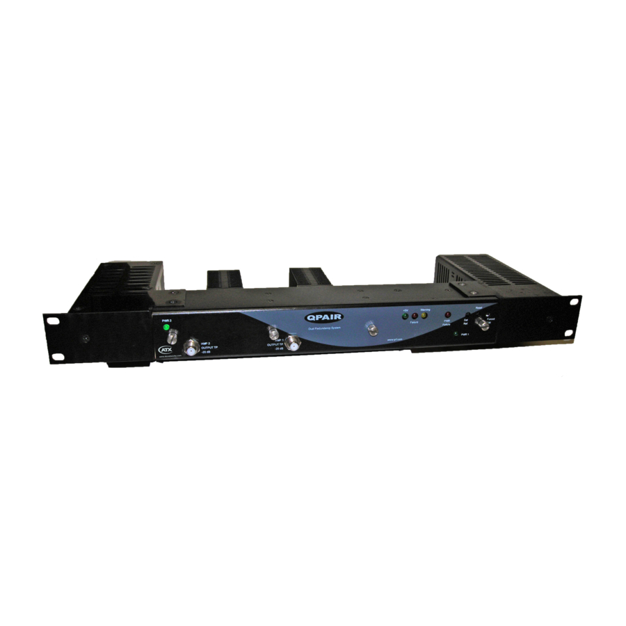
Please refer to the following picture for illustration.
Main Signal
Input
1-2
Main Signal
Output
Q-Series
Amplifiers – QPAIR Redundant Amplifier System – Installation & Operation Manual
®
