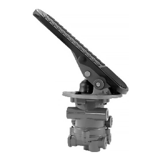
BENDIX E-15 Handbuch - Seite 7
Blättern Sie online oder laden Sie pdf Handbuch für Kontrolleinheit BENDIX E-15 herunter. BENDIX E-15 8 Seiten. Dual brake valve

DISASSEMBLY
The following disassembly and assembly procedure is pre-
sented for reference purposes and presupposes that a major
rebuild of the brake valve is being undertaken. Several re-
placement parts and maintenance kits are available which
do not require full disassembly. The instructions provided
with these parts and kits should be followed in lieu of the
instructions presented here.
Caution: The brake valve may be lightly clamped in a
bench vise during disassembly, however, over clamping
will result in damage to the valve and result in leakage and/
or malfunction. If a vise is to be used, position the valve so
that the jaws bear on the delivery and supply ports on
opposing sides of the valve's upper body.
1. Remove all air line fittings and plugs.
2. Mark the relationship of the upper and lower body (a
scribed line can be used) then remove the four cap
screws (16) that secure the lower body to the upper
body. Separate the two body halves and remove and
discard the o-ring (17).
3. Pull the secondary piston (18) out of the upper body and
remove and discard the o-rings (19 & 20) from it.
4. Remove and discard the special beveled retaining ring
(10) from the lower body while manually holding and
compressing the valve seat (11) in place.
5. Slowly release the valve seat (11), allowing it to rise out
of the body. Remove the valve seat (11) then remove and
discard the o-ring (12).
6. Remove and discard the valve assembly (13) along with
its o-ring (15) from the lower body. Remove the valve
assembly return spring (14).
7. Carefully remove and discard the exhaust diaphragm
retainer (24) and exhaust diaphragm (25) from the lower
body.
Note: Some E-12
™
& E-15
exhaust ports in lieu items 24 & 25.
8. Using finger force, push the piston (2) into the body until
the piston retaining ring (1) is fully visible. Remove the
piston retaining ring (1), taking care not to damage the
piston bore in the body.
9. Gently tap the body on a soft surface to remove the
piston (2). Remove and discard the o-rings (3 & 5) and
both wear rings (4) from the piston (2).
10. Place the piston on a flat surface and using finger force,
depress and hold the spring retainer (7), then remove
and discard the retaining ring (6) from the piston (2).
11. Gently release the spring retainer (7), allowing it to rise
out of the piston. Remove the spring retainer (7) and
graduating spring (8) from the piston (2).
™
brake valves have threaded
12. Remove and discard the rubber spring (9) from the
interior of the piston (2).
Note: The rubber spring (9) is installed in the E-12
brake valve only.
13. Remove and discard the special beveled retaining ring
(10) from the piston (2) while manually holding and
compressing the valve seat (11) in place.
14. Slowly release the valve seat (11), allowing it to rise out
of the piston (2). Remove the valve seat (11), then
remove and discard the o-ring (12).
15. Remove and discard the valve assembly (13) along with
its o-ring (15) from the piston (2). Remove the valve
assembly return spring (14).
CLEANING & INSPECTION
1. Using mineral spirits or an equivalent solvent, clean and
thoroughly dry all metal parts.
2. Inspect the interior and exterior of all metal parts that
will be reused for severe corrosion, pitting and cracks.
Superficial corrosion and or pitting on the exterior por-
tion of the upper and lower body halves is acceptable.
3. Inspect the bores of both body halves for deep scuffing
or gouges.
4. If the primary piston (2) is to be reused make certain
that vents "A & B" are open and free of obstructions.
5. Make certain vent "C" is open in the upper body of the
valve.
6. Inspect the pipe threads in both body halves. Make
certain they are clean and free of thread sealant.
7. Inspect the treadle or pedal assembly and mounting plate
which attaches to the basic valve. Make certain that
the treadle or pedal roller turns freely and is lightly
lubricated.
Note: Some treadle/pedal assemblies, not furnished by
Bendix, do not employ a roller in which case make cer-
tain the mechanism in use moves across the plunger
smoothly without binding or sticking. Inspect the plunger
for excessive scuffing and wear. Check the plunger bore
in the mounting plate for excessive wear as exhibited by
"egg shaping." Inspect the mounting plate for severe
corrosion paying particular attention to the area around
the pedal or treadle fulcrum pin bores.
8. When applicable (in use), check the rubber boot installed
between the plunger and mounting plate for deteriora-
tion or cracking. Replace if necessary.
9. Inspect all air line fittings and plugs for corrosion. Clean
all old thread sealant from the pipe threads.
Any valve or treadle assembly component exhibiting a con-
dition described in inspection steps 1 to 9 should be discarded
and replaced before proceeding.
™
7
