HIGHLY LIQUID MD24 Benutzerhandbuch - Seite 10
Blättern Sie online oder laden Sie pdf Benutzerhandbuch für Aufnahmegeräte HIGHLY LIQUID MD24 herunter. HIGHLY LIQUID MD24 10 Seiten.
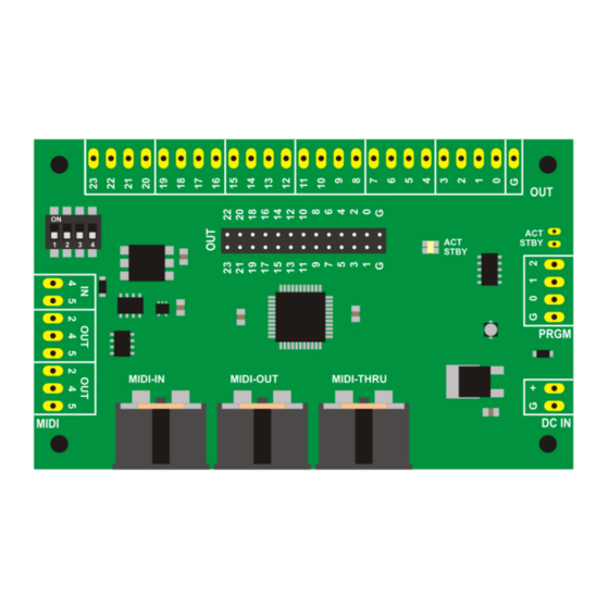
Highly Liquid
MD24 Hardware Revision G
8.3 Servo Wiring
Each MD24 output can be configured as a "servo mode" output. A servo mode output generates a 5V
pulse width modulation (PWM) servo control signal. See MD24 Firmware User Manual for more details.
A servo has three leads: ground, power input, and control input ("signal"). Each lead is identified by
color: ground is usually black, blue or brown; power input is usually red; and signal is usually white,
yellow, or orange. Exact colors vary by servo brand and model.
MD24-to-servo wiring is shown in Figure 8.2. Output #18 is used as an example, but the circuit can be
connected to any servo mode output. Repeat as needed for each servo/MD24 output pair.
The MD24 provides only the control signal. The power supply for the servo must be provided separately.
See the documentation provided by the servo manufacturer for power supply requirements. Most RC
servos will operate using a 5VDC or 6VDC power source.
Figure 8.2: Servo Output Wiring
© 2011 Sonarcana LLC
Page 10 / 10