AFL FR1-SM-150-SC-SC Handbuch - Seite 2
Blättern Sie online oder laden Sie pdf Handbuch für Prüfgeräte AFL FR1-SM-150-SC-SC herunter. AFL FR1-SM-150-SC-SC 2 Seiten. Otdr fiber rings

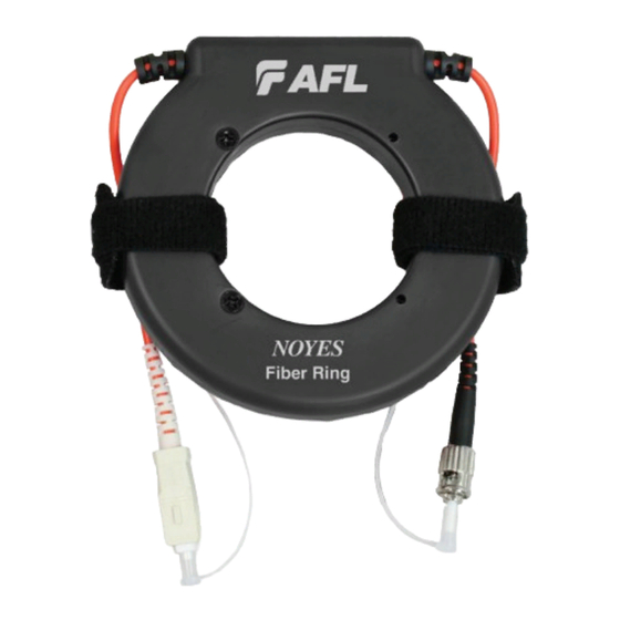
OTDR Fiber Rings
How to Generate a Baseline Trace Using Fiber Rings
•
Use the Fiber Ring as a launch cable.
Connect the Fiber Ring between your OTDR and the fiber link under test. This will allow
you to measure the loss of the near-end connection.
•
Use the Fiber Ring as a receive cable.
Connect the Fiber Ring to the far-end connector of your fiber link under test. This will
allow you to measure the loss of the far-end connection.
•
By using Fiber Rings as both launch and receive cables, as shown in the diagram below,
you can measure total insertion loss of the fiber link under test.
Fiber ring - launch cable
Fiber ring connector
1
OTDR port
OTDR
OTDR port
Near-end connection
Fiber ring - launch cable
Fusion splice
2
Fiber link under test
6
Fusion splice
3
Near-end connection
Example OTDR Test Configuration with Launch and Receive Cables
1
2
3
4
OTDR Trace Made using Launch and Receive Cables
International Sales and Service Contact Information
4
5
Far-end connection
© 2014, AFL, all rights reserved. FR00-00-2000 Revision 1D, 2014-10-24
2
Fiber ring - receive cable
7
8
End of receive cable
End of receive cable
8
6
Fiber link under test
Far-end connection
5
7
Fiber ring -
receive cable
Specifications are subject to change without notice.
