AFL Hyperscale U Series Installationshandbuch - Seite 13

Blättern Sie online oder laden Sie pdf Installationshandbuch für Netzwerk-Hardware AFL Hyperscale U Series herunter. AFL Hyperscale U Series 17 Seiten. Front-access v-panel
Auch für AFL Hyperscale U Series: Installationshandbuch (8 seiten), Installationshandbuch (16 seiten), Installationshandbuch (8 seiten), Installationshandbuch (8 seiten), Installationshandbuch (12 seiten), Installationshandbuch (8 seiten), Installationshandbuch (8 seiten), Installationshandbuch (20 seiten), Installationshandbuch (20 seiten), Installationshandbuch (16 seiten)
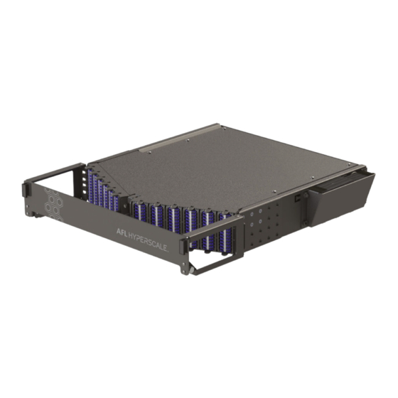
AFL Hyperscale U Series Installationshandbuch
Cable Installation
Cable Fiber
Slack Loop
Cable Braid
Cable
Tie-Off Point
Cassette
Identification
Labels
Splice Tray 1 (BOTTOM): Tie off cable braid to splice tray. Starting with internal pigtail #1
24
fiber (GREEN), place splice protector into
Cable Fiber
Slack Loop
Cable Braid
Cable
Tie-Off Point
Splice Tray 2 (TOP): Tie off cable braid to splice tray. Starting with internal pigtail #7
25
fiber (GREEN), place splice protector into
Series
Splice Tray 1
(Bottom Tray)
YELLOW
YELLOW
holder. Coil fiber in suggested route shown.
Splice Tray 2
(Top Tray)
holder. Coil fiber in suggested route shown.
U-Series 2RU Front-Access V-Panel (FVP)
Internal SWR
Fiber Slack Loop
(Pre-Installed)
Tail
Identification
Labels
(RED),
splice to cable
Internal SWR
®
Pigtail
Fiber Slack Loop
(Pre-Installed)
Tail
Identification
Labels
Cassette
Identification
Labels
(RED),
splice to cable
© AFL Hyperscale. All rights reserved
®
Pigtail
13