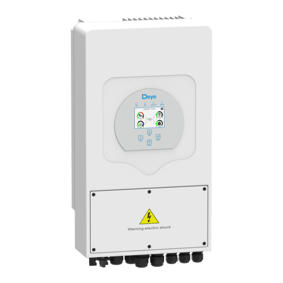
Deye SUN-3.6K-SG03LP1-EU Benutzerhandbuch - Seite 5
Blättern Sie online oder laden Sie pdf Benutzerhandbuch für Inverter Deye SUN-3.6K-SG03LP1-EU herunter. Deye SUN-3.6K-SG03LP1-EU 19 Seiten. Hybrid inverter

6
Current transformer (Optional)
7
Battery sensor
8
L-type Hexagon wrench
9
Wall mounting bracket
Chart 3-1 Parts List
3.2 Mounting instructions
Installation Precaution
This Hybrid inverter is designed for outdoor use(IP65),Please make sure the installation
site meets below conditions:
・ Not in direct sunlight
・ Not in areas where highly flammable materials are stored.
・ Not in potential explosive areas.
・ Not in the cool air directly.
・ Not near the television Antenna or antenna cable.
・ Not higher than altitude of about 2000 meters above sea level.
・ Not in environment of precipitation or humidity(>95%)
Please AVOID direct sunlight, rain exposure, snow laying up during installation and
operation. Before connecting all wires,please take off the metal cover by removing
screws as shown below:
Considering the following points before selecting where to install:
・ Please select a vertical wall with load-bearing capacity for installation, suitable for
installation on concrete or other non-flammable surfaces,installation is shown below.
・ Install this inverter at eye level in order to allow the LCD display to be read at all times.
1
1
1
1
- 05 -
・ The ambient temperature should be between -25~60℃ to ensure optimal operation.
・ Be sure to keep other objects and surfaces as shown in the diagram to guarantee
sufficient heat dissipation and have enough space for removing wires.
For proper air circulation to dissipate heat, allow a clearance of approx. 50cm to the side
and approx.50cm above and below the unit.And 100cm to the front.
Mounting the inverter
Inverter should vertically installed, as shown,installation procedure show below:
1. Position the bolts on the appropriate wall according to the bolt positions on the
mounting shelves and mark the holes. On the brick wall, the installation must be
suitable for the expansion bolt installation.
2.Ensure that the position of the installation holes on the wall (A, B, C, D) are the same
position of the install plate, and the mounting level is guaranteed.
3. Hang the inverter to the top of the mounting rack and then use the M4 screw in the
accessory to lock E and F to ensure that the inverter does not move.
≥500mm
≥500mm
- 06 -
