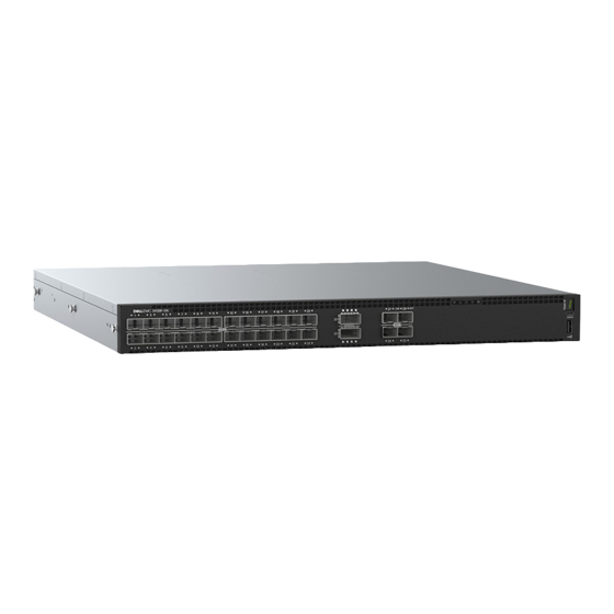
Dell S4148F-ON Series Installationshandbuch - Seite 17
Blättern Sie online oder laden Sie pdf Installationshandbuch für Schalter Dell S4148F-ON Series herunter. Dell S4148F-ON Series 47 Seiten.
Auch für Dell S4148F-ON Series: Installationshandbuch (48 seiten)

The cabinet must meet minimum size requirements. Airflow must be in accordance with the Electronic Industries Alliance (EIA) standard.
Ensure that there is a minimum of 5 inches (12.7 cm) between the intake and exhaust vents and the cabinet wall.
Rack mounting
When you prepare your equipment rack, ensure that the rack is grounded. Ground the equipment rack to the same ground point the power
service in your area uses. The ground path must be permanent.
Switch ground
Dell EMC recommends grounding your switch. Use the S4100–ON Series switch in a CBN.
Fans and airflow
The fans on the S4100–ON Series (S4128F-ON and S4148F-ON) support two airflow options: normal and reverse.
Fan combinations
Fan installation is done as part of the factory install based on SKU type. The S4100–ON Series has stock keeping units (SKUs) that support
the following configurations:
•
AC PSU with fan airflow from the I/O to the PSU—normal
•
AC PSU with fan airflow from the PSU to the I/O—reverse
•
DC fan unit with airflow from the I/O to the PSU—normal
•
DC fan unit with airflow from the PSU to the I/O—reverse
Be sure to order the fans suitable to support your site's ventilation. Use a single type of airflow fan in your switch. Do not mix reverse and
normal airflows in a single switch.
For proper ventilation, position the S4100–ON Series switch in an equipment rack or cabinet with a minimum of 5 inches (12.7 cm) of
clearance around the exhaust vents. The fan speed varies based on internal temperature monitoring. The switch never intentionally turns
off the fans.
For more information, see Fans.
Power
Connect the switch to the applicable power source using the appropriate power cable. An AC power cable is included with the system.
When installing AC or DC switches, follow the requirements of the National Electrical Code ANSI/NFPA 70, where applicable.
The switch is powered-up when the power cable is connected between the switch and the power source.
For more information, see
Power
CAUTION:
Always disconnect the power cable before you service the power supply slots. The switch has multiple power cords.
Before servicing, ensure all power cords are disconnected.
CAUTION:
On the AC switch, use the power supply cable as the main disconnect device. Ensure that the socket-outlet is
located/installed near the equipment and is easily accessible.
NOTE:
Module power is software controlled. You do not see module LEDs when the switch powers up in ONIE.
supplies.
Site preparations
17
