Allmand 10-000001 Schnellstart-Handbuch - Seite 4
Blättern Sie online oder laden Sie pdf Schnellstart-Handbuch für Industrielle Ausrüstung Allmand 10-000001 herunter. Allmand 10-000001 17 Seiten.

SERIAL NUMBER 10-000001 & 11-000001
** * Units with LSC modules (digital display screens/ Auto start) have a smaller
120 transformer that plugs into pin#16 of LSC. Check power from main breaker
all the way up to pin#16 for correct voltage.***
Lights fail to Illuminate.
❏ Check power at the main breaker. Power should be 120/240 from the gen to the main
breaker. If power is lower than recommended rating, check the capacitor and generator
output.
❏ If power is 120 at the main breaker, proceed to the light switched and light relays. Each
light breaker should have the same voltage at the main breaker (120/240) and current
should pass through each light relay. If voltage is found to drop then fix or replace the
breaker or the light relay.
❏ Power is tested good at both light and switches, ensuring ballast is receiving sufficient
voltage in ( @ 120/240). Power out of ballast to the capacitor and light circuit should
measure 360-440 volts (+/ - 10%) is within spec. * *If a voltage test yields high voltage
other than normal at lamp output to light then this is an indication that the
light/tower cord has a short (Example- 500-600 volts indicates backfeeding
through tower cord due to short in circuit).
Testing generator output at the GFCI receptacle:
W ARNING: Dangerous voltage and/or current may be present when a
voltage test is being conducted. To reduce the risk of serious injury or death from
electrical shock, if you are not trained to safely work with high voltage, do not attempt
any of these procedures. You must seek assistance from qualified personnel.
Generator output voltage may be tested by using a multimeter to measure the voltage
across the terminals of the GFCI power receptacle.
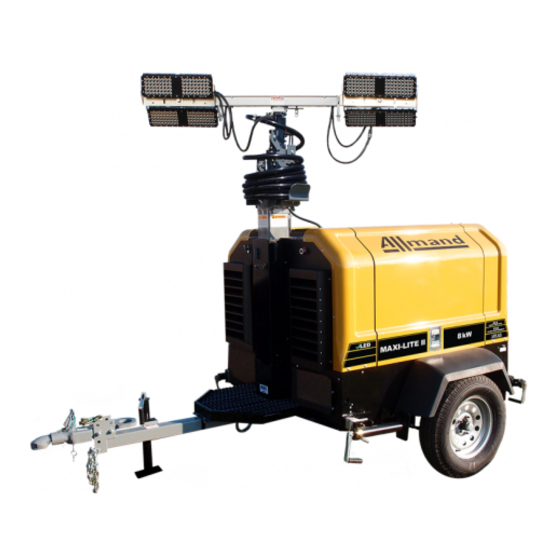
MAXI LITE II
