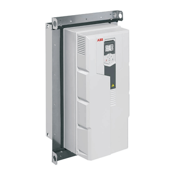
ABB ACS580-01 +C135 Series Handbuch zur Schnellinstallation - Seite 2
Blättern Sie online oder laden Sie pdf Handbuch zur Schnellinstallation für Industrielle Ausrüstung ABB ACS580-01 +C135 Series herunter. ABB ACS580-01 +C135 Series 2 Seiten. Frames r4 and r5 flange mounting kit

6
R4 IP21 (UL Type 1) only
Remove the control panel (a) and cover (b) to install the auxiliary fan (ordering code
3AXD50000034334). Cut off the protective plate from the fan slot (c) and install the fan
(d). Make sure that the arrow on the fan points outwards. Connect the fan cable to FAN2.
a
b
R4: X6
9
10
7
Drill holes for M6 Rivet or Kalei nuts. Consider the hole size for the nuts.
Rivet/Kalei nuts are not included in the delivery.
Note: The mounting templates are different (size, number and position of
holes) for different frame sizes.
c
f
e
d
11
1 × M6×25 screw
1 × M6×25 screw
6 N·m (4.4 lbf·ft)
6 N·m (4.4 lbf·ft)
ACS580-01...+C135, ACH580-01...+C135 and ACQ580-01...+C135 frames R4 and R5 flange mounting kit quick installation guide
i
13
12
1 4 × M6×25 screw
6 N·m (4.4 lbf·ft)
8
UL Type 12 only
UL Type 12 is fulfilled on the drive backside when the flange and hood
are installed. Hood is not required for IP55.
3 x M6 nuts
6 N·m (4.4 lbf·ft)
Back
Front
For dimensions, see the mounting
template delivered with the flange
mounting kit or
ACS580-
01...+C135, ACH580-01...+C135 and
ACQ580-01...+C135 drives with
flange mounting kit supplement
(3AXD50000349821 [English]).
ACS580-01 manuals
Go to
www.abb.com/drives.
ACH580-01 manuals
ACQ580-01 manuals
2
h
Hood (view from top)
Hood (view from
bottom)
