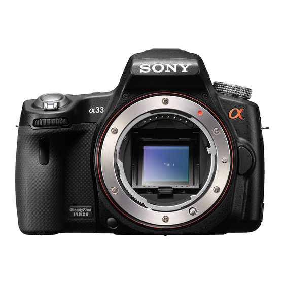
Sony SLT-A33Y Service-Handbuch - Seite 5
Blättern Sie online oder laden Sie pdf Service-Handbuch für Digitalkamera Sony SLT-A33Y herunter. Sony SLT-A33Y 30 Seiten. Interchangeable lens digital camera/zoom lens kit

1-1. METHOD FOR REPLACING THE P.O.I.
Method of Removal
(1) Press the MB Mirror Frame Holder Lock SP to raise the P.O.I.
MB Mirror Frame Holder Lock SP
(2) Unjoint the two claws while pressing the P.O.I. backward.
P.O.I.
Claw
Claw
1-2. PRECAUTION ON REPLACING THE AM-022 BOARD
Destination Data
When you replace to the repairing board, the written destination data of repairing board also might be changed to original setting.
USB Serial No.
The set is shipped with a unique ID (USB Serial No.) written in it.
This ID has not been written in a new board for service, and therefore it must be entered after the board replacement.
SLT-A33/A33L/A33Y/A55/A55V/A55L/A55VL/A55VY_L2
Method of Attachment
(1) When attaching the P.O.I., make the concave side of it face the
front and attach it downward.
P.O.I.
Concave side
Claw
1. SERVICE NOTE
1-3. METHOD FOR CHECKING THE AS SLIDER UNIT (863)
Make sure to confirm below before replacing the AS Slider B Assy or the AS Holder Actuator Assy.
(1) Remove the CV Rear Cover Assy (863), and temporally mount the AS Slider Unit (863).
(2) Set the AS Slider Unit (863) upwards as shown in figure, and put it on a stable place.
Claw
(3) Select "Slider Unit Check" of the adjustment software, and then confirm the movement to the directions of Pitch and Yaw, and if an error occurs,
replace it with the component part corresponding to the movement.
1-1
– ENGLISH –
