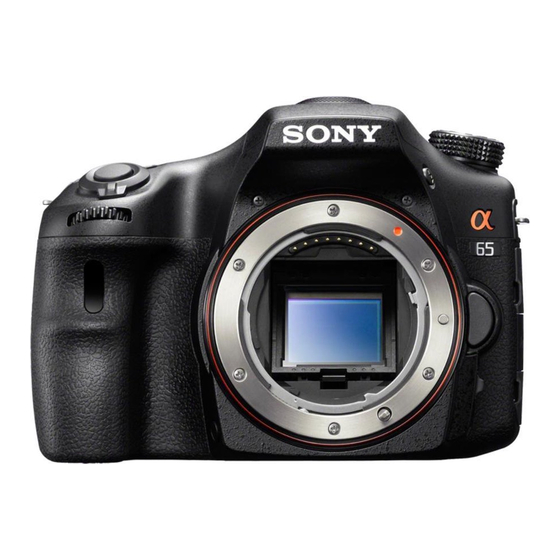
Sony SLT-A65X Service-Handbuch - Seite 8
Blättern Sie online oder laden Sie pdf Service-Handbuch für Digitalkamera Sony SLT-A65X herunter. Sony SLT-A65X 36 Seiten.

Ver. 1.2 2012.04
The changed portions from
Ver. 1.1 are shown in blue.
1-6. METHOD FOR REPLACING THE AS SLIDER B ASSY
Removal Procedure
(1) Remove the spring.
Spring
(2) Remove the solder on the enamel wires at two places.
Solder
Solder
(3) Remove the flexible board from the AS Slider B Assy.
Flexible Board
(4) Remove the two screws.
(5) Remove the AS Unit Holder Ball.
AS Unit Holder Ball
(6) Remove the two Ball Bearings.
Ball Bearing
Ball Bearing
SLT-A65/A65K/A65L/A65M/A65V/A65VK/A65VL/A65VM/A65VX/A65VY/A65X/A65Y_L2
(7) Remove the Cap SPs (for Pitch and Yaw).
Cap SP
(8) Remove the Caps (for Pitch and Yaw).
Cap
(9) Remove the AS Slider A Assy.
It can be done easily if A is removed beforehand.
A
AS Slider A Assy
(10) Remove the AS Slider B Assy.
It can be done easily if B is removed beforehand.
B
AS Slider B Assy
(11) Remove the three Ball Bearings.
Ball Bearing
Assembly Procedure
Note: Make sure to perform the assembly procedures after assembling the AS Holder Actuator Assy.
The assembly procedure is the reverse of the removal procedure.
Apply grease to the portions indicated below.
* After applying grease, attach the Ball Bearings.
Ball Bearing
G G-15
G G-15 and G G-116
AS Slider B Assy
* After applying grease, attach the Ball Bearings.
Ball Bearing
G G-15
Ball Bearing
G G-15
1-4
– ENGLISH –
