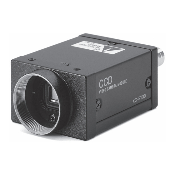
Sony XC-ST51 Technisches Handbuch - Seite 13
Blättern Sie online oder laden Sie pdf Technisches Handbuch für Digitalkamera Sony XC-ST51 herunter. Sony XC-ST51 30 Seiten. Black-and-white video camera module
Auch für Sony XC-ST51: Handbuch (4 seiten)

Using trigger pulse width
Set all DIP switches (1 to 4 on the rear panel) to 0.
You can obtain an arbitrary shutter speed by setting the
trigger pulse width within the range of 2 µ sec to 250
msec.
Mode 1 (Non-reset mode)
Exposure time = Trigger pulse width + 97 µ sec (EIA)
Trigger pulse width + 120 µ sec
(CCIR)
Notes
• The DIP switch 5 position is optional. (The field
setting is recomended.) The field setting can obtain a
sensitivity that is twice that of the frame setting.
• If you input another trigger pulse before the video
signal output for the previous trigger pulse is
completely output, an incorrect video signal will be
output.
• Specifications of trigger pulse
When using a trigger pulse like shown below, set
the TRIG polarity selector switch on the rear panel
to + :
2 µsec – 1/4 sec
1) If you set the trigger pulse with the DIP switches, use the
100 msec to 1/4 sec pulse width.
XC-ST51/ST51CE
XC-ST50/ST50CE
XC-ST30/ST30CE
Mode 2 (Reset mode)
2 – 5.0 V
0 – 0.6 V
1)
When using a trigger pulse like shown below, set
the TRIG polarity selector switch on the rear panel
to – :
2 µsec – 1/4 sec
• Input impedance: 10 kΩ or more.
• The voltage and pulse width used are measured at pin
11 of a 12-pin multi-connector on the rear panel.
Mode Settings
4.0 – 5.0 V
0 – 2.0 V
13
