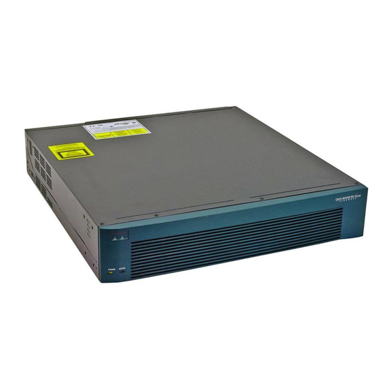
Cisco PIX 525 Benutzerhandbuch - Seite 3
Blättern Sie online oder laden Sie pdf Benutzerhandbuch für Netzwerk-Hardware Cisco PIX 525 herunter. Cisco PIX 525 30 Seiten. Security appliance
Auch für Cisco PIX 525: Datenblatt (13 seiten)

Chapter 6
PIX 525
Figure 6-4
Figure 6-4
100Mbps
Table 6-2
Table 6-2
LED
100 Mbps
ACT
LINK
The PIX 525 has RJ-45, network and console connectors, as well as a DB-15 Failover cable connector.
The USB port is not used at this time.
Installing the PIX 525
To install the PIX 525, perform the following steps:
Step 1
The PIX 525 provides one set of brackets for installing the unit in an equipment rack. Complete these
steps if the unit is going to be installed into an equipment rack:
a.
b.
78-15170-02
shows the PIX 525 rear panel LEDs.
PIX 525 Rear Panel LEDs
ACT(ivity)
ACT(ivity)
LED
LED
LINK
LED
LED
100Mb ps ACT
LINK
100Mb ps ACT
10/1 00 ETH ERN ET 1
10/1 00 ETH ERN ET 0
10/100 BaseTX
Ethernet 1
(RJ-45)
10/100 BaseTX
Ethernet 0
(RJ-45)
lists the states of the PIX 525 rear panel LEDs.
PIX 525 Rear Panel LEDs
Color
State
Green
On
Off
Green
Flashing
Green
On
Attach the brackets to the holes near the front of the unit on each side of the PIX 525 using the
supplied screws.
Attach the unit to the equipment rack.
LINK
Failover
LED
connector
F
A
I
L
O
V
E
R
LINK
PIX-52 5
USB
CON SOL E
USB
port
Console
port (RJ-45)
Description
Port 100 megabits per second 100BaseTX communication.
Port is using 10 megabits per second data exchange.
Shows network activity.
Shows that data is passing through that interface.
Cisco PIX Security Appliance Hardware Installation Guide
Installing the PIX 525
6-3
