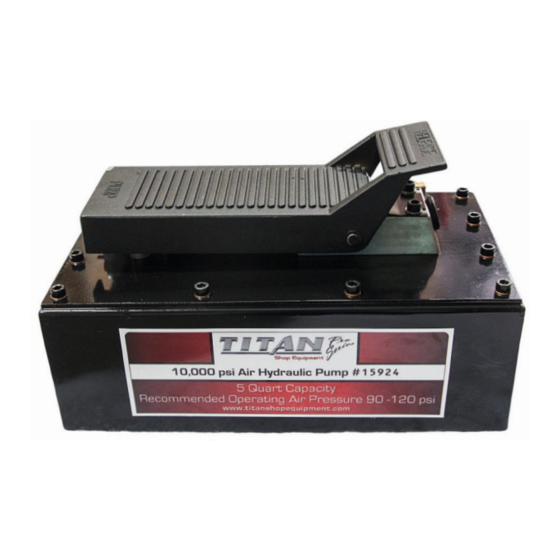
AME 15924 Manual de instrucciones y desglose de piezas - Página 2
Navegue en línea o descargue pdf Manual de instrucciones y desglose de piezas para Bomba de agua AME 15924. AME 15924 6 páginas. 5 quart air/hydraulic pump, steel reservoir
También para AME 15924: Manual de instrucciones y desglose de piezas (4 páginas)

INSTRUCTION MANUAL
& PARTS BREAKDOWN
SPECIFICATION
DESCRIPTION
tools. It consists of an in-line air and hydraulic cylinder. The ratio of
100:1. In other words, 100 PSI out of every 1 PSI in – 100 PSI input
air pressure equals 10,000 PSI output pressure.
RELEASE
Depressing the RELEASE pedal causes a decrease in pressure and
BEFORE USE
To prevent oil leak during shipment, a metal knob is installed
and tightened to ensure the best sealing function.
Loosen it
counterclockwise befo re use.
Note:
Note : Always secu re threaded port connections with non-ha r dening pipe thread
compound. T ighten secu rely to prevent accidental removal of components while in
chart on above for details of oil port th
read size, usable oil capacit
y, and mo r e.
OPERATION
Operation of the unit is as follows:
1. Connect the hose of the Air/Hydraulic Pump to the hydraulic
coupling on the selected tool.
2. Connect the air supply line to the Air/Hydraulic Pimp.
Air
supply should be 5-10 CFM at 100 PSI to obtain proper operating
characteristics. In addition, the air line should be equipped with an
3. Stepping on the PUMP end of the pedal engager the pump,
producing the fo rce necessary to run the tool.
4. Depressing the RELEASE end of the pump pedal will release the
pressure
AME INTERNATIONAL
- 2 -
