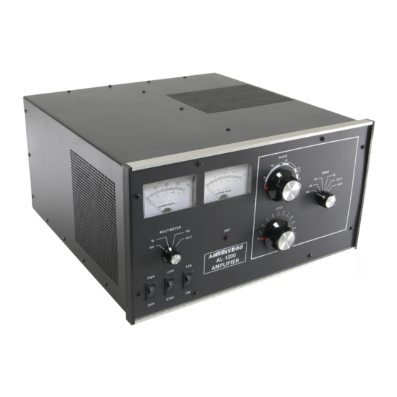
AMERITRON AL-1200 Manual de instrucciones - Página 6
Navegue en línea o descargue pdf Manual de instrucciones para Amplificador AMERITRON AL-1200. AMERITRON AL-1200 15 páginas. Full power linear amplifier

TRANSFORMER INSTALLATION Cont.
For 220V connections(see Fig. 3), follow these steps
1. Slide the RED boot back
wire
2. Clip the terminal connector off the wire and
slide the RED boot off
3. Remove the restraint from the GRN wire and
slide the RED boot on to the wire.
4. Solder the terminal connector to the GRN wire.
5. Tape up the BRN/WHT wire because it will
not be used.
TUBE INSTALLATION
Note that one of the tube pins is offset. This offset pin
"keys" the tube base and socket. Install the tube by
aligning the tube pins with the socket contact terminals,
then seat the tube with vertical pressure ONLY. Do not
"rock" or "twist" the tube
Place the chimney over the tube anode with the large
opening down. DO NOT FORCE the chimney down over
the anode. Carefully lower the chimney with an even
pressure until it seats outside the four metal retaining
clips on the socket.
on
the BRN/WHT
Fig. 3
TUBE INSTALLATION Cont.
After the chimney is installed, attach the anode
connector as follows: (Refer to the Fig. 4)
1. Remove screw "A" that holds the anode con-
nector to the 500pf blocking capacitors. 2.
Attach the anode connector to the tube Anode.
Position it so screw "A" can be re-installed.
3. Snug down nut "B" just enough to prevent
the anode connector from sliding.
4. Insert screw "A" into the 500pf capacitors
and snug it down.
Recent production model AL-1200 amplifiers have a
neutralization tab located next to the 3CX-1200A7. This
change results in additional efficiency on 21 and 28
MHz.
This tab should not be altered in position. In the event
the tab becomes displaced, proper neutralization will
occur when the maximum output power and grid current
and minimum plate current appear concurrently.
This adjustment is obtained by changing the tab to tube
spacing. BE SURE TO REMOVE AC POWER FROM
THE AMPLIFIER AND ALLOW BLEEDERS TO
DISCHARGE POWER BEFORE REMOVING THE
COVER. NEVER DISCHARGE AMPLIFIER HV TO
THE CHASSIS WITH A SCREWDRIVER OR A
"CROWBAR".
A 100 ohm 10 watt resistor may be clipped from ground
to the HV.
Fig. 4
