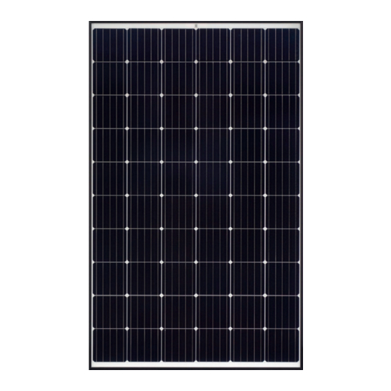
Astronergy CHSM6612M Manual de instalación - Página 14
Navegue en línea o descargue pdf Manual de instalación para Equipamiento industrial Astronergy CHSM6612M. Astronergy CHSM6612M 19 páginas. Crystalline silicon pv
También para Astronergy CHSM6612M: Manual de instalación (10 páginas), Manual de instalación (12 páginas), Manual de instalación (12 páginas), Manual de instalación (18 páginas), Manual (19 páginas)

CHSM72M-HC
CHSM72P-HC
CHSM72M/LV-HC
CHSM72M(BL)-HC
CHSM66M-HC
CHSM66M(BL)-HC
6
Electrical Installation
6.1
Electrical characteristics
The electrical characteristics are detailed in the PV
module product manual.
The rated values of electrical characteristics, including
I
, V
and P
, have some tolerance with the
sc
oc
mpp
measured values at standard condition: ± 5% for I
± 3% for V
and ± 3% for P
oc
condition refers to 1000W/m
temperature at 25℃.
According to IEC and UL standards, the standard
maximum system voltage for the regular module series
is 1000V, the 1500V standard products are also
available according to the requirements. The IEC &
UL standard maximum system voltage for half-cell
module series is 1500V (except for BL &LV series PV
modules).
The actual maximum voltage must be less than the
standard maximum system voltage and the maximum
output voltage of the inverter and other electrical
equipment installed in the system. The number of PV
modules connected in series should match the voltage
14
2018*1002*40
+5400Pa
2018*1002*35
-2400Pa
2108*1048*35
+5400Pa
2094*1038*35
-2400Pa
2256*1133*35
+5400Pa
2279*1134*35
-2400Pa
2278*1134*35
+5400Pa
2384*1303*35
-2400Pa
. The standard test
mpp
2
, AM1.5 and cell
+5400/-2400Pa
+2400Pa
Installation scope
-2400Pa
350± 50mm
+5400/-2400Pa
+2400Pa
Installation scope
-2400Pa
400± 50mm
+5400/-2400Pa
+2400Pa
Installation scope
-2400Pa
400~450mm
+5400/-2400Pa
+2400Pa
Installation scope
-2400Pa
475~525mm
specification of the inverter. The total voltage
generated by PV modules in series should not be
higher than the maximum voltage allowed by the
system.
To ensure the above requirements, the open-circuit
voltage of the string needs to be calculated at the
lowest expected ambient temperature at certain
location. This can be calculated using the following
,
sc
formula:
Maximum system voltage≥N*V
Where:
N: number of PV modules in a single string
V
: open-circuit voltage of each PV module (refer to
oc
the PV module nameplate or product manual)
TC
: temperature coefficient of PV module for
voc
open-circuit voltage (refer to the PV module product
manual)
T
: minimum ambient temperature.
min
!ATTENTION
+2400Pa
---
-2400Pa
+Bumper
+2400Pa
---
-2400Pa
+Bumper
+1800Pa
---
-1800Pa
+Bumper
+1800Pa
---
-1800Pa
+Bumper
*[1+TC
*(T
-25)]
oc
voc
min
