Atkinson Electronics GSCM-MINI Manual - Página 7
Navegue en línea o descargue pdf Manual para Unidad de control Atkinson Electronics GSCM-MINI. Atkinson Electronics GSCM-MINI 16 páginas. Generator start control module
También para Atkinson Electronics GSCM-MINI: Manual (8 páginas)

GSCM-mini-d Relay
9. During shutdown, K2 relay closes to ensure the shutdown of the generator by grounding out the ignition, etc. It
remains closed until the AC Hz signal from the generator has gone to zero for 5 seconds to ensure that the generator
has shutdown.
10. The generator remains off until another start signal is received.
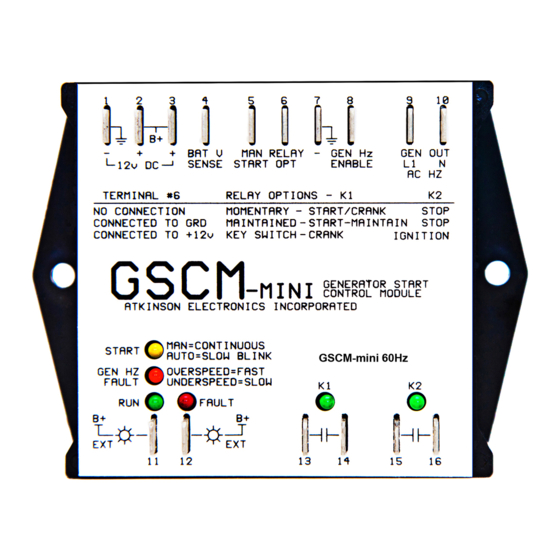
GSCM-mini-d Relay Option 2
The configuration terminal 6, has been connected to ground (terminal 7) which configures the GSCM-mini-d for maintained
start sequence. The GSCM-mini is then powered by connecting B+ (12.0 VDC) to terminal 2. The Start LED turns on for 5
seconds while the GSCM-mini initializes with option #2 maintained starting sequence then begins blinking the start LED once
every 5 seconds. The generator starting sequence is as follows.
1. The start LED blinks once every 5 seconds to indicate that the GSCM-mini is in a ready mode. When a manual start
signal is received, the start LED lights continuously. After a 2 second delay, K1 relay closes to start the generator. The
K1 relay remains closed until either the start signal is removed or the maximum cranking time of 1 minute is reached.
2. If the generator fails to start after a single 1 minute start period, GSCM-mini runs thru its shutdown routine, the fault
LED turns on and the GSCM-mini enters the maximum crank lockout condition and the generator Hz LED does a
double blink. This lockout condition remains until the GSCM-mini is reset by removing power from terminal 2 (see
GSCM-mini wiring diagram page 4), waiting 5 seconds and reconnecting power. This clears the lockout condition, and
returns to ready mode.
3. When the generator starts, K1 relay remains energized. A valid run condition is determined by one of two conditions:
a 12V run status pilot light signal provided by the generator connected to terminal 8, or by the generators AC output
frequency exceeding the crank disconnect setting of 45Hz (terminals 9 & 10) and is indicated by the run LED being
turned on.
4. If the generator starts but shuts down after a few seconds due to a fuel problem, etc. The GSCM-mini goes thru its
shutdown routine then re-enters ready mode after a 60 second delay. During this delay the start LED will blink rapidly.
The GSCM-mini will then try to start the generator again in manual mode or after a 5 minute delay period in auto-
start mode.
5. When a run condition is detected, the GSCM-mini turns on the run LED and open collector transistor output (remote
run lamp) and after a 60 second generator stabilization period begins monitoring the AC Hz signal for over/ under Hz
condition.
6. If the generator starts but shuts down after the 60 seconds stabilization period, due to a fuel problem, low oil
pressure, broken AC Hz or 12V run pilot light status wire, the GSCM-mini blinks the generator Hz LED for an under Hz
condition, after 60 seconds the run LED turns off, K2 relay energizes for 5 seconds, and fault LED turns on and the
generator Hz LED blinks four times every two seconds. The GSCM-mini enters a fault shutdown lockout condition and
must be powered down to reset the fault lockout.
7. If no faults occur, the generator continues running until one of the following occurs: The manual start signal is no
longer received, the auto battery charge voltage or maximum run time has been reached while running in auto charge
mode, an over or under Hz condition occurs if generator Hz shutdown is enabled or the generator runs out of fuel.
8. Shutdown routine, K1 de-energizes, then ½ second later K2 relay energizes, remains closed until the AC Hz signal from
the generator goes to zero for 5 seconds ensuring generator shutdown.
9. The generator remains off until another start signal is received.
www.atkinsonelectronics.com
800.261.3602
Momentary Starting Sequence Continued
Maintained Starting Sequence
7
Circuit Board Division
Revised 11/2020
