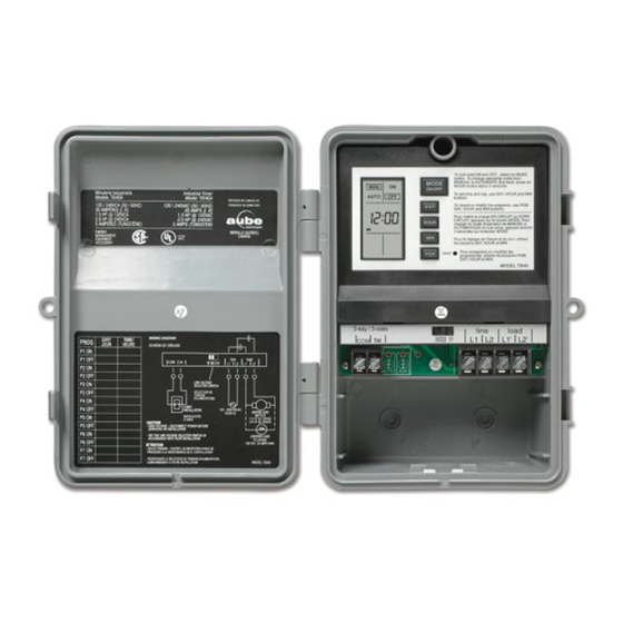
Aube Technologies TI040 Manual de instalación y uso
Navegue en línea o descargue pdf Manual de instalación y uso para Timer Aube Technologies TI040. Aube Technologies TI040 4 páginas. Industrial indoor / outdoor timer
También para Aube Technologies TI040: Manual de instalación y uso (2 páginas), Manual de instalación y uso (4 páginas)

About your new timer
• Line voltage selector switch (120/208/240V)
• Can function as a regular switch or as a programmable timer
• Up to 7 programs (7 on settings / 7 on settings) per week
• A single-pole switch can be connected to the timer to control the
load similar to a 3-way installation. For example, the timer can be
installed outside whereas the switch can be located remotely (e.g.,
inside the house)
• Can be used in various applications (see table below)
Load type
Maximum load
Resistive
30 A
load
Inductive
10 A
load
1.5 hp @ 120 VAC
Motor
2.0 hp @ 240 VAC
Installation
Cut power at the main electrical panel to avoid electric shock.
Open the TI040 door and remove the plastic cover to access the
mounting holes and wire terminals.
Install the TI040 to a vertical surface such as a wall by means of
three screws (not supplied).
WARNING: To prevent rain infiltration or any other liquid from
the top, the TI040 must be installed in the upright position as
shown above.
Remove the necessary knockouts at the bottom of the housing.
Install strain-relief bushings over the knockouts, pass the wires
through the bushings and secure them in place.
Perform the connections as shown on the wiring diagram.
NOTE: For a 3-way installation only, connect a regular single-
pole switch to the 3-way terminals of the timer as shown on the
wiring diagram.
TI040
Examples
•
incandescent lights
•
halogen lights
•
block heater
•
fluorescent lights
•
compact fluorescent lights (CFL)
•
sodium lamps
•
electronic ballasts
•
pool filter pumps
•
fans
Knock-out
Select the proper input voltage by means of the voltage selector
1.
switch. (WARNING: Failure to do so can damage the product.)
Reinstall the plastic cover and apply power at the main electrical
panel.
Single-pole switch
(for 3-way installation)
Power-up
Mode display
2.
Program number
At power-on, 0:00 should flash. Otherwise, press reset using a paper
clip. If the display is blank, verify the power supply.
Setting the clock
NOTE: The switch displays the time in 24-hour format by default or
following a reset.
To change to 12-hour format (or vice versa), proceed as follows:
a) Press the MODE button to ensure the MAN or AUTO indica-
tor is displayed.
b) Press the MIN and HOUR buttons simultaneously and briefly
(0:00 display = 24-hour, 12:00 display = 12-hour).
Set the time using the HOUR and MIN buttons. If you have
selected the 12-hour format, ensure that PM appears on the
screen when an afternoon time is displayed.
Set the day by using the DAY button.
Press the MODE button to return to normal operation.
Installation and User Guide
Industrial Indoor / Outdoor Timer
Line voltage
selector
switch
Power supply
(120/208/
240 VAC)
On/Off display
• Briefly press the button to
turn the load On or Off.
• Press the button for 3
seconds to switch
between Automatic mode
and Manual mode.
Insert a paperclip
to reset the timer.
TI040
Motor
Lighting
3.
4.
1/2
