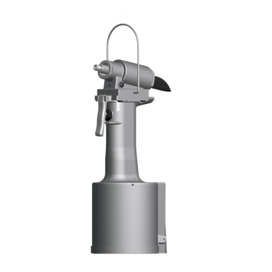
Gage Bilt GB704 Manual - Página 7
Navegue en línea o descargue pdf Manual para Herramientas Gage Bilt GB704. Gage Bilt GB704 14 páginas. Installation tool
También para Gage Bilt GB704: Manual de instalación (13 páginas), Manual de instrucciones original (20 páginas)

FILLING & BLEEDING PROCEDURE:
NOTE:
Air Bleeder Assy (704153) and fill bottles(745263) are required.
NOTE:
To replace a small amount of oil follow BLEEDING steps 5-6.
WARNING:
Do not cycle tool without air bleeder assy (704153), or the button head cap screw (402482) and stat-o-seal (S572),
installed in tool head. Severe personal injury could result.
CAUTION:
Before filling handle assy (704132), air piston assy (704121) should be all the way down.
CAUTION:
When forcing piston rod assy (704138) downward, with head cylinder assy (704183) removed, hydraulic oil will eject
forcibly from handle assy (704132).
WARNING:
Failure to follow these instructions carefully may result in severe personal injury
IMPORTANT:
Be sure to use thread sealant on all hydraulic fittings, Loctite® 30534 or similar Teflon® infused pipe dope is
recommended.
Teflon may enter the hydraulic system and cause malfunction or damage. Use 1 1/2 wraps of tape on each thread.
Cut off all loose tape ends. Tighten until fitting feels snug and then go 1/2 to a full turn past that point.
Over tightening can easily distort the threads.
* FILLING & BLEEDING VIDEO AVAILABLE AT: www.gagebilt.com/bleeding.htm
FILLING:
1.
Put the piston rod wrench (704149) into the top of handle assy (704132), pushing down firmly until piston rod ass'y (704138) is completely in
the down position.
CAUTION:
When forcing piston rod assembly downward, with head cylinder assy removed, hydraulic oil will eject forcibly from handle assy.
2.
Fill oil passage and reservoir with Automatic Transmission oil Dexron III or equivalent. The reservoir is the area surrounding the
power cylinder (751131). When looking at the top of the handle assy (704132) the oil passage is the hole that has a counter bore
for o= ring (S832). Do not overfill causing oil to go in air passage hole.
3. Re-install o= ring (S832), gasket (704129), button head cap screws (A-928) and manifold-handle (744303) to handle assy (704132), keeping
hydraulic hose (A-336) towards plug (704313), located on handle assy (704132). Torque button head cap screws (A-928) to 40 inch lbs.
4.
Push piston (704507) full forward. Install gasket (704129), o= ring (S832) and socket head cap screws (400061 & 400066) on
manifold-head assy (744306). Assemble head cylinder assy (704183) to manifold-head assy (744306). Apply Loctite 242 to all
cap screws and torque socket head cap screws (400061 & 400066) to 40 inch lbs.
5.
Remove lever assy (724017) from manifold-head assy (744306).
on side so that the hole marked #3 on the manifold-handle (744303) is to the top. Set manifold-head assy (744306) over a small
bucket or can. Completely fill up fill bottle (745263).
6.
Remove button head cap screw (402482) and stat-o-seal (S572) from manifold-handle (744303) hole #3 and manifold-head assy
(744306) hole #4. Connect fill bottle (745263) to manifold-handle (744303) hole marked #3.
7.
In one continuous squeeze force oil into manifold-handle (744303) until oil starts to flow from bleeder hole marked #4 on the
manifold-head assy (744306). While still squeezing the fill bottle (745263) use other hand to replace button head cap screw
(402482) and stat-o-seal (S572) on the manifold-head assy (744306). Torque 35-40 inch lbs. This may require two people.
8.
Remove fill bottle (745163) and replace stat-o-seal (S572) and button head cap screw (402482) on manifold-head assy (744306)
and torque 35-40 inch lbs.
BLEEDING:
1.
Ensure lever assy (724017) is removed from manifold-head assy (744306).
and head cylinder assy (704183) upward and lay flat on a table or bench. When bleeding tool always keep the head cylinder assy
(704183) higher than the handle assy (704132).
2.
Remove Button Head Cap Screw (402482) and Stat-o-seal (S572) from manifold-handle (744303) hole marked #3. Attach air
bleeder assy (704153) to manifold-handle (744303) hole marked #3 in an upright position.
3.
Connect the tool to air supply and cycle tool ten times holding the air actuator assy (704130) down for 2-3 seconds between
cycles to remove any air from the tool.
4. Disconnect air supply. Remove air bleeder assy (704153) from manifold-handle (744303) and replace with button head cap screw
(402482) and stat-o-seal (S572) and torque 35-40 inch lbs.
5.
Remove button head cap screw (402482) and stat-o-seal (S572) from hole marked #4 on manifold-head assy (744306) and attach
air bleeder assy (704153) in an upright position.
6.
Connect air supply. Cycle tool ten times removing any air bubbles.
7.
Disconnect air supply. Remove air bleeder assy (704153) and replace button head cap screw (402482) and stat-o-seal (S572) on
manifold-head assy (744306) and torque 35-40 inch lbs.
8.
Connect air supply. Cycle tool ten times and check stroke of .540" (13.72mm) (see diagram below). We recommend using dial
calipers. With the air actuator assy (704130) released, check dimension (A). Holding air actuator assy (704130), check dimension
(B). If stroke is not consistent within 1/64" (.0156") repeat bleeding steps 5-6.
9.
Re-attach lever assy (724017) to manifold-head assy (744306).
S/N: 1090 AND ABOVE
PLEASE CONTACT GAGE BILT FOR ALL OTHER SERIAL NUMBERS.
CAUTION:
Teflon tape is an excellent thread sealer, however, if it is not properly applied, pieces of
.740 (18.8mm)
Coil tool hoses up on bench and lay handle assy (704132) down
Stand handle assy (704132) on floor, stretch tool hoses
'B'
.200 (5.1mm)
7
CAUTION:
Rev. 11/14
