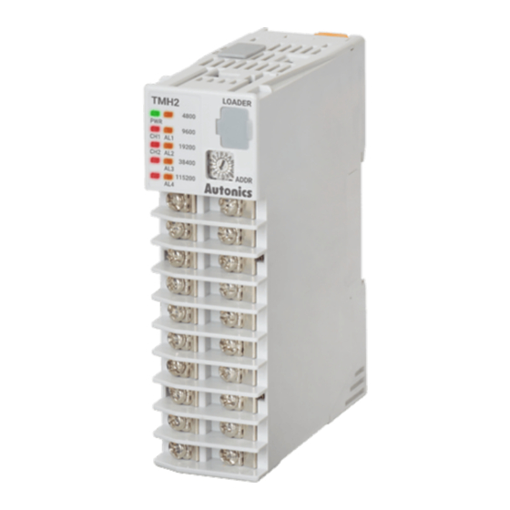
Autonics TMH Series Manual de inicio rápido - Página 4
Navegue en línea o descargue pdf Manual de inicio rápido para Controlador de temperatura Autonics TMH Series. Autonics TMH Series 6 páginas. Modular2/4-channel pid temperature controllers with screw connector

Installation Method
■ Separating base terminal block
②
①
• When connecting base terminal block, align the upper concave part (凹) of the body
and the upper convex part (凸) of the base. If the upper parts are not align correctly, it
may damage to the inner connector.
■ Connection between modules
Basic
Expansion
②
module
module
①
③
④
⑤
• Supply adequate power for power input specifications and overall capacity.
(Max. power when connecting 32 modules: 32 × 5 W = 160 W)
■ Mounting with bolts
①
1. Refer to 'Separating base terminal block' to separate base
terminal block.
2. Install the module by using M4 screws to the ① direction of the
inside mounting hole.
M4
• Refer to the 'Dimensions' to check hall positions and dimensions
①
of inside mounting hole.
■ Mounting on DIN rail
- Installation
①
1. Press the rail lock at the top / bottom of the module to the ①
direction.
①
①
2. Hang the top rail lock to DIN rail.
3. Push to ① direction and press to ② direction.
②
- Separation
①
1. Press the module to ① direction.
2. Keep it pressed and pull it to ② direction.
②
■ Precautions
• Install the module vertically.
• Use end plates (sold separately, not available from Autonics) to fix firmly.
Error
Indicator
Description
Name Status Color
□ channel error: Input value < Input range,
PRW
ON
Red
CH□
Flash
Red
Sold Separately
• Communication converter: SCM-series
• Current transformer (CT)
1. Push the lock lever at ①.
2. Pull the body of the module to ②
direction.
1. Remove END cover (①)
of each module
(except END cover of the
first and last module).
Expansion
2. ② Insert expansion
module
connector (②) and
connect them tightly
to ③ direction (max. 31
units).
3. Insert module lock
connector (④) to lock
⑥
connector hole (⑤).
4. Push module lock
connector to the lock
direction (⑥).
Troubleshooting
When the error
Input value > Input range,
factor is resolved, it
Input sensor is open or not
automatically returns
connected
to normal operation.
CICT4-□
• CT connector cable:
Connections
■ Control module
TMH2/4: 1 to 10 terminal
TMH2: 11 to 20 terminal TMH4: 11 to 20 terminal
CH1
A
1
11
B
2
12
+
+
+
㎃
V
-
-
-
B'
3
13
RTD
TC
OUT1
4
14
+
+
Relay,
㎃
V
Current,
5
15
-
-
SSR
A
CH2
6
16
B
7
17
+
+
+
㎃
V
B'
-
-
-
8
18
RTD
TC
9
19
OUT2
+
+
Relay,
㎃
V
Current,
10
20
-
-
SSR
Terminal Function 1 Function 2
Terminal Function
1
A -
11
CH1
2
B TC,
+
12
RTD
input
current,
13
3
B'
-
voltage
14
4
Relay,
+
15
CH1
current,
-
output
5
-
16
SSR
17
6
A -
18
CH2
7
B TC,
+
RTD
19
input
current,
8
B'
-
20
voltage
9
Relay,
+
CH2
current,
-
output
10
-
SSR
CT input terminals on the top
Back
Front
CT connecter cable
Pin Cable color CT connection
1
Brown
CT 2 / 4
2 4
2
Blue
CT 2 / 4
3
White
CT 1 / 3
4
Black
CT 1 / 3
1 3
■ Option module
TMHA [Analog input / output]
CH1
A
1
11
-
㎃
B
+
2
12
+
+
+
㎃
V
-
-
-
B'
B'
3
13
RTD
TC
B
4
14
+
TC
Transfer1
㎃
A
-
OUT
5
15
RTD
A
CH2
6
16
-
㎃
+
B
7
17
+
+
+
㎃
V
-
-
-
B'
B'
8
18
RTD
TC
B
9
19
+
Transfer2
TC
㎃
OUT
A
-
10
20
RTD
11
DIGITAL
㎃
V
IN1
12
B'
13
-
AL1 OUT
+
B
14
TC
AL2 OUT
A
15
RTD
16
DIGITAL
㎃
V
IN2
17
B'
18
-
AL3 OUT
B
+
19
TC
AL4 OUT
A
20
RTD
Terminal Function 1 Function 2
11
Relay,
CH3
Digital input 1
current,
12
output
SSR
Alarm output 1
13
Ground
CH3
14
Alarm output 2
RTD
input
15
Digital input 2
16
Relay,
CH4
Alarm output 3
current,
output
17
Ground
SSR
Alarm output 4
18
CH4
19
RTD
input
20
Power/Comm. terminal on the back
[Basic module]
CT4
+
CT3
CT2
CT1
CH3
Terminal Function 1 Function 2
1
A -
Transfer3
CH1
2
B TC, current,
RTD
OUT
input
3
B'
4
+
CH1
Current
-
-
-
output
5
-
㎃
V
6
A -
+
+
+
CH2
7
RTD
B TC, current,
input
8
B'
9
+
CH2
Current
output
10
-
CH4
11 CH3
-
Current
output
Transfer4
12
+
OUT
13
A -
CH3
14
RTD
B TC, current,
input
15
B'
-
-
-
16 CH4
-
㎃
V
Current
+
+
+
output
17
+
18
A -
CH4
19
RTD
B TC, current,
input
20
B'
CH3
OUT3
Relay,
Current,
SSR
-
-
㎃
V
+
+
CH4
OUT4
Relay,
Current,
SSR
-
-
㎃
V
+
+
-
-
+
B' -
B TC,
-
current,
A
+
voltage
-
-
+
B' -
B TC,
-
current,
A
+
voltage
24 VDCᜡ
-
SG
+
voltage
-
-
+
voltage
-
-
-
-
voltage
+
-
-
voltage
+
