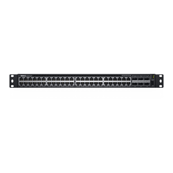
Dell S4048T-ON Manual de introducción - Página 22
Navegue en línea o descargue pdf Manual de introducción para Interruptor Dell S4048T-ON. Dell S4048T-ON 35 páginas.

5
DC power source wires—black, green, blue
1
Strip 1/2 inches of insulation from each of the site's DC power source wires, item 5.
2
Insert each of the site's DC power source's bare wire lengths into the wiring block,
matching wire colors, items 3 and 4.
WARNING:
blue, green aligns with green, and black aligns with black.
3
Use a flat-blade screwdriver to tighten the screws that secure the bare wires into the
wiring block.
4
Insert the DC power connector cable end into the power socket of the DC PSU and
tighten the thumb screws, items 1 and 2.
WARNING:
PSU power socket.
NOTE:
To remove the power connector from a DC PSU, unscrew the thumb screws
and pull the power connector from the DC PSU socket.
Installing a Fan Module
The four fan modules and the power supplies are hot-swappable if you install a second
(redundant) power supply.
NOTE:
To run the system, the four fan slots must have operating fan units. If you do
not install a module in each slot, the system shuts down in one minute.
NOTE:
The system supports two airflow direction options. You can only use a single
direction in a chassis.
•
Normal is airflow from the I/O side to the power supply.
•
Reversed is airflow from the power supply to the I/O side.
There are environmental factors that could decrease the amount of time required between
fan replacements. Check these environmental factors regularly. Any unusual environmental
circumstance at the site that causes an increase in temperature and/or particulate matter in
the air might affect performance (for example, new equipment installation).
1
Remove the fan module from the shipping box.
2
Use the grab handle to slide the module into the switch fan slot.
22
Hardware installation
Do not cross the wires—In the wiring block, blue aligns with
Never try to force the power connector into or out of the DC
