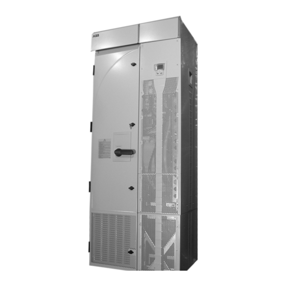
ABB ACS550-U2 Manual del suplemento de instalación - Página 10
Navegue en línea o descargue pdf Manual del suplemento de instalación para Controlador ABB ACS550-U2. ABB ACS550-U2 16 páginas. Drive it low voltage ac drives 150...550 hp

10
7. The following cables between the drive and the
extension module are split by a connector located
at the front of the drive. Disconnect both cables at
this location.
• The power supply cable to the OMIO board.
• The power supply cable to the extension
module cooling fan.
8. At the OTIF board, disconnect the two fiber optic
cables. Make note of the terminal colors for use
when reconnecting.
9. Carefully remove the cables disconnected in the
above steps: Pull the cables down inside the
pedestal and bundle them so that they will not get
damaged or caught in the trolley when the drive
module is wheeled out.
10. Remove screws fastening the drive module trolley
to the pedestal.
Warning! These screws are an important step
during re-assembly – the screws are required for
grounding the drive.
11. R8: The front of the trolley includes support
braces that fold out. Lift each brace slightly and
fold it out.
12. Remove screws that fasten the drive module to
the extension module.
CAUTION! The drive module is now separated
and could tip over. Use care when moving the
drive module.
13. Pull on the handle to wheel the drive module out.
Drive Maintenance
See the ACS550-02/U2 User's Manual for drive
maintenance procedures.
Re-Assembly
Re-attach the modules in reverse order to the above.
Maintenance
Installation Supplement for ACS550-U2 Drives
R7
7
8
R7
13
10
10
9
12
Pedestal
Trolley
