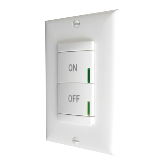
Acuity Brands SensorSwitch sPODM Series Manual - Página 2
Navegue en línea o descargue pdf Manual para Interruptor Acuity Brands SensorSwitch sPODM Series. Acuity Brands SensorSwitch sPODM Series 2 páginas. Sensor interface switch

A1
TYPICAL CONFIGURATIONS
Bi-Level Solution w/ Occupancy Sensor: 1-gang
BI-LEVEL (MANUAL ON / AUTO ON) SOLUTION
w/ OCCUPANCy SENSOR: 1 GANG
sPODM 2P
WHT / BLU STRIPE
BLU / WHT STRIPE
BLK
RED
BLU
WHT
A2
RED
BLK
WHT
BI-LEVEL (AUTO-ON / MANUAL ON) SOLUTION
Bi-Level Solution w/ Occupancy Sensor: 2-gang
w/ OCCUPANCy SENSOR: 2 GANG
sPODM
WHT / BLU STRIPE
BLK
RED
WHT
WHT
RED
BLK
WHT
RED
BLK
WHT / BLU STRIPE
sPODM SA
PROGRAMMING INSTRUCTIONS
1.
Enter programming mode by pressing & holding upper most button until LED flashes rapidly. Release button.
2.
Enter the On Mode function by pressing button twice.
3.
The current On Mode setting will then be fed out in a sequence of LED flashes as indicated in the table below (e.g., one flash for Auto-
On). To change the setting, proceed to step 4 before sequence repeats 10 times.
4.
At any time while the switch is flashing back the current On Mode setting, interrupt it by pressing button the number of times for the new
desired On Mode setting as indicated in the table below (e.g., press twice for Manual On). Switch will begin to flash back new setting as
confirmation.
5.
Next, while the switch is flashing back new setting, interrupt it by pressing and holding button until LED flashes rapidly. Release button.
6.
As final confirmation and activation of the new setting, press button two times.
7.
LED will flash twice indicating acceptance of new setting. If two flashes are not seen, repeat 7 step process.
Note: To exit programming mode without saving, wait for blink back sequence to repeat 10 times then return to step 1.
Function
Number
2
900 Northrop Road, Wallingford, CT 06492 • 1.800.PASSIVE • FX 203.269.9621 • www.sensorswitch.com
(note: 3 conductor 18AWG wire is recommended for all wiring)
N
H
BLK/ORN
WHT
WHT
PP20
BLU
BLK
BLU
AUTO ON
RED
LOAD
A4
BLK/ORN
WHT
WHT
PP20
BLU
BLK
BLU
AUTO ON
RED
LOAD
Class 1 Connections
SP20
RED
MANUAL
BLU
BLK
ON LOAD
BLU
WHT
H
Function
Name
Setting Number
1
2
On Mode
3
(2P devices only)
4
(2P devices only)
WARRANTY:
months. Sensor Switch, Inc., upon prompt notice of such defect, will, at its option, provide a Returned Material Authorization number
and repair or replace returned product.
LImITATIONS ANd ExCLUSIONS:
(including the implied warranties of merchantability and fitness for use) and under no circumstances shall Sensor Switch, Inc. be liable
for any incidental or consequential property damages or losses.
MANUAL ON w/ DIMMING & OCCUPANCy SENSOR
Class 1 Connections
WHT
SP20
BLK
BLU
BLU
RED
MANUAL
ON LOAD
3-Way Manual On Solution w/ Occupancy Sensor: 1-gang
H
N
3-WAy MANUAL ON SOLUTION w/ OCCUPANCy SENSOR
WHT
sPODM SA 3X
WHT
Note: SPODM (SA) 3X D units should only be used in 3-way applications with SPODM (SA)
3X units (non-dimming) as dimming levels are not communicated between devices.
(PLeASe reAD ALL 7 STePS BeFOre PrOGrAMMING)
Settings (*indicates default setting)
Pole 1
Auto-On
Manual On
Manual On
Auto-On
Sensor Switch, Inc. warrants these products to be free of defects in manufacture and workmanship for a period of 60
This Warranty is in full lieu of all other representation and expressed and implied warranties
3-Way Manual On Solution w/ Occupancy Sensor: 1-gang
Revised 06.20.14 © 2014 Sensor Switch
WHT
RED
BLK
WHT
sPODM SA D
BLK
WHT
BLK
RED
WHT / BLU STRIPE
VIO
If sensor also has dimming output, connect sensor VIO wire to SPODM and ballast VIO wire
Note: If sensor also has dimming output, connect sensor VIO wire
to SPODM and ballast VIO wire. Lowest output level always takes
precedence.
Class 1 Connections
WHT
BLK
RED
BLK
BLK
RED
WHT / BLU STRIPE
YEL
YEL / BLK STRIPE
Pole 2
(2P devices only)
Manual On
Auto-On
Manual On
Auto-On
Class 1 Connections
H
N
BLK / ORN
WHT
PP20
BLU
BLU
0-10 VDC
BALLAST
GRY
VIO
RED
H
N
BLK / ORN
WHT
PP20
BLU
BLU
LOAD
RED
sPODM SA 3X
BLK
RED
WHT / BLU
YEL
YEL / BLK STRIPE
WHT
TS-SPOd-002B
