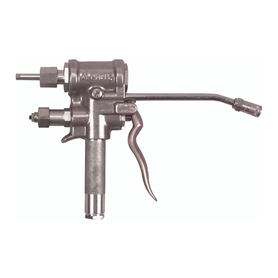
Alemite 7716-D1 Manual de servicio - Página 8
Navegue en línea o descargue pdf Manual de servicio para Unidad de control Alemite 7716-D1. Alemite 7716-D1 12 páginas. High-pressure measuring control valve

SER 7716-D1
24. Screw Packing Screw (35) into the Valve Body.
• Tighten securely.
25. Grease Valve Actuation Stem (39).
CAUTION
Do not install the Valve Actuation Stem small
diameter first. Damage to the Seals can occur.
26. Install the Valve Actuation Stem [large diameter first]
through the rearward Washer and Seal first.
• Use a small hammer.
27. Install Valve Guide (23) over the Valve Actuation Stem
and onto the Slide Valve.
• Make sure the Valve Guide seats properly on the
Stem.
28. Cycle the Stem to ensure the Slide Valve moves freely
and functions properly.
29. Screw Retainer (15) into the Valve Body.
30. Install Washer (16) into the Retainer.
31. Install Spring (17) into the Retainer.
CAUTION
Overcome Spring pressure with Cap (18) before
installation. Cross-threading can occur.
32. Screw Cap (18) onto the Retainer.
33. Screw Setscrew (19) halfway into the Cap.
34. Install Nut (20) onto the Setscrew.
• Do not tighten.
35. Align Lever (24) to the Valve Body,
36. Secure the Lever to the Valve body with Pin (38).
• Use a small hammer and make sure the knurled end
of the Pin is flush with the Valve Body.
37. Screw Setscrew (37) into the Lever.
38. Install Nut (36) onto the Setscrew.
• Do not tighten.
Setscrew Adjustment (Lever Free-Play)
Adjust the Setscrew against the Valve Body until a
0.010 to 0.030 " [0.25 - 0.76 mm] clearance exists between
the end of the Valve Actuation Stem and the surface of the
Lever. Use a feeler gauge. See Figure 4.
Revision (11-95)
High-Pressure Measuring Control Valve
Setscrew
Nut
Stem
Lever
0.010 - 0.030 "
(0.25 - 0.76 mm)
Figure 4 Lever Free-Play
Turn the Setscrew clockwise to increase the amount of
free-play and counterclockwise to decrease the gap.
Tighten the Nut securely.
Inlet Handle
39. Install O-Ring (27) onto Inlet Handle (28).
• Make sure the O-ring does not roll.
40. Screw and seat Stud (31) into Bushing (29).
41. Install Gasket (30) onto the Bushing.
42. Install and seat Strainer (32) onto the Bushing.
43. Position Retaining Washer (33) over the Stud and onto
the Strainer.
44. Screw Knurled Nut (34) onto the Stud.
• The top of the Stud should be flush with top of the
Knurled Nut.
45. Screw the Inlet Handle assembly into the Valve Body
and tighten securely.
• Use a strap wrench or other suitable tool that will not
mar the surface of the Inlet Handle.
46. Screw Extension (40) into the Valve Body.
• Make sure the head of the Extension points toward
the Inlet Handle.
47. Screw Coupler (41) onto the Extension and tighten
securely.
48. Screw Plug (11) into the Valve Body and tighten
securely.
8
Valve
Body
Alemite Corporation
