AluTeam BR 248-2 Manual de instrucciones de montaje - Página 5
Navegue en línea o descargue pdf Manual de instrucciones de montaje para Camiones AluTeam BR 248-2. AluTeam BR 248-2 12 páginas. Box body kits

AluTeam kits can be assembled in any well-
equipped workshop. Carry out the following
preparations beforehand.
Attention:
3. Assembling the kit on the floor
Series 248-2 Assembly Instructions
If you use adhesives or
sealants other than those
supplied by AluTeam, you
are responsible for the
seals and bonding carried
out with these alternative
products. No warranty is
provided for them.
2.4 Preparations
• Check the delivery
(1.1) and check that the bottom rail of the
walls as well as the floor section are undamaged. Damage can make
the assembly difficult or even impossible!
• Note and follow the safety instructions and warnings
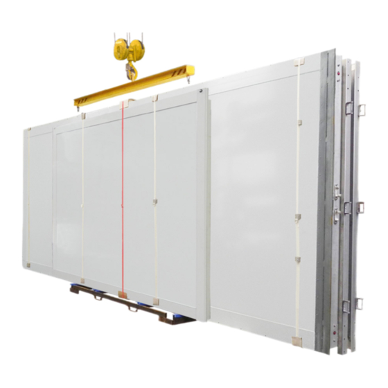
In particular, secure the overall kit against toppling, as well as the
individual assemblies. These are stored on the pallet in the order
they are required to assemble the body. Therefore, do not cut the red
straps securing one component each until the assembly is removed.
sufficient free space
•
Provide
in front of and behind the vehicle or assembly area and the required
Tools and Equipment
ambient temperature
•
The
at least
sealants must be
•
The following describes off-vehicle preassembly. To this end, carry
out the assembly on a level floor. To protect the painted components
and to make alignment easier, place e.g. wooden panels 300 x 300
mm (at least 20 mm thick) or similar on the floor under the corners
of the front wall / side wall and side wall / rear frame.
3.1 Assembling the walls
•
Use a crane and lifting gear or a vacuum lifting beam to remove the
front wall (bulkhead) from the transport unit and carefully place it
on the plywood boards.
Danger:
Toppling assemblies are at risk to life and limb.
The wall therefore remains secured, e.g. in the crane.
•
Remove the first side wall in the same way and push it onto the
front wall at right-angles.
Attention:
The corner pillars must not be closed off at the bottom,
as it may be necessary to lay cables through them later.
•
One fitter secures the components on the outside. The 2nd employee
MD100224 (torque 10 Nm ± 1) up to a approx. ¾ of the box height,
starting at the bottom, until the sections are pressed together. If
necessary, use punches as an assembly aid.
•
Remove the second wall (as described above) from the transport
rack. Position the wall and align it at right-angles with the front
wall; the wall remains hanging from the crane initially.
•
Now screw in 3 - 4 screws MD100224 again, starting from the bottom
up to approx. ¾ of the box height, until the sections are pressed
together and the required torque (10 Nm ± 1) is reached.
Dated 11/2021
Previous instructions become invalid.
(at lest 3 m) on both sides, as well as
(2.2) .
for components as well as adhesives and
15°C.
(1.2 & 1.3).
5 / 12
