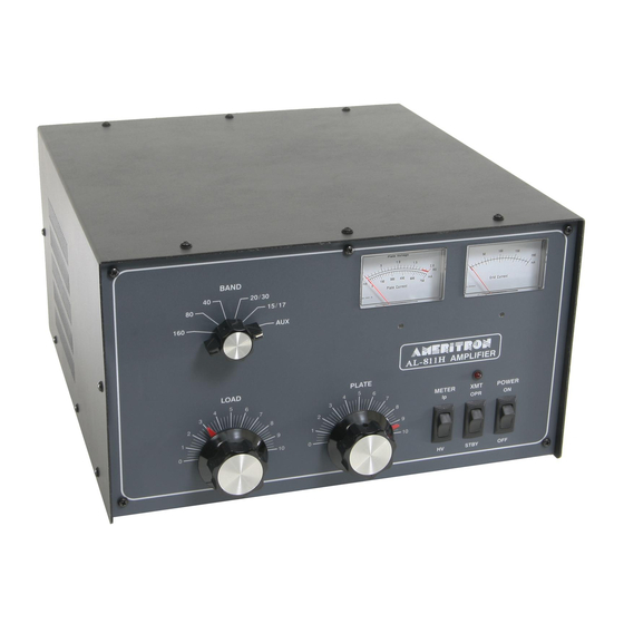
AMERITRON AL-811HXCE Manuel - Page 3
Parcourez en ligne ou téléchargez le pdf Manuel pour {nom_de_la_catégorie} AMERITRON AL-811HXCE. AMERITRON AL-811HXCE 13 pages.
Également pour AMERITRON AL-811HXCE : Informations complémentaires (2 pages)

SAFETY INTERLOCK
The interlock switch stays closed to allow AC line voltage to
reach the power transformer as long as the AL-811H's top cover
is in place. When the top cover is removed, the interlock opens
and disconnects the input line voltage. This does not discharge
the bank of power supply filter capacitors. Be sure to allow the
filter capacitors to discharge before you touch anything inside
the amplifier. You can select the High Voltage function of the
Multimeter to check the high voltage potential.
WARNING: never remove the cover of this amplifier with
the unit plugged into the power line.
DRIVING POWER
This amplifier is designed to operate at full ratings when it is
driven by an exciter that has approximately 70 watts of RF
output. You can use an exciter that has lower output power, but
the amplifier's output may be less. If you use an exciter that
delivers more than 70 watts, carefully adjust the driving power
to avoid "over drive" and the creation of spurious signals, which
could create needless interference to other operators. We highly
recommend that you use a monitor scope for continuous output
monitoring. The display on an oscilloscope is the best readily
available way of determining the amplitude of the voice peaks
which, if excessive, can cause "flat topping" and splatter.
IMPORTANT: Do not increase the drive power unless the
amplifier output power also increases. Grid current climbs
rapidly and the plate current meter and output power will
barely increase with excessive drive.
indicates the amplifier LOAD control needs to be advanced
to a higher number. Excessive plate current indicates the
drive power limit has been reached. Non-linear operation,
splatter, and excessive grid current will occur if the
"LOAD" setting it too low.
FILAMENT SUPPLY
The filament circuit of this amplifier satisfies all requirements of
the tube manufacturer related to tube performance and life.
Inrush current is controlled by the transformer's internal
resistance and impedance, filament choke resistance, and
filament wiring resistance. To insure maximum life of the tube,
never replace any circuit components or wiring with substitute
parts.
ALC CIRCUIT
The ALC circuit converts a portion of the RF drive voltage at
the exciter end of the tuned input circuit to a negative going
control voltage. This voltage should be used to limit the exciter
drive to safe drive levels for the
develop more than
70 watts of output power.
A capacitive divider consisting of C27 and C28 is used to reduce
the RF voltage and drive a rectifier circuit consisting of D17 and
D18. The resulting voltage is filtered by C29 and R12 and is
applied to the ALC potentiometer R14. R13 provides RF and
DC isolation for the ALC jack. The DC isolation prevents
loading of the exciter ALC input line by the ALC potentiometer.
The ALC circuit can be adjusted by loading the AL-811H
slightly beyond the recommended maximum values with the
3
GENERAL INFORMATION
This condition
AL-811H for exciters that
ALC line disconnected. The ALC line can then be connected
and the ALC control on the amplifier can be adjusted to a point
just before the drive begins to decrease.
NOTE: The primary use of the ALC function is the prevention
of excessive drive levels. This circuit will not prevent small
changes in output power from occurring on different bands.
Under most conditions destructive levels of drive power are
those above 100 watts. Slight changes may occur in maximum
output power on different frequencies with the ALC connected.
A compromise in ALC adjustment may be necessary to achieve
acceptable performance on all bands.
PLATE SUPPLY
The power supply in this amplifier uses a combination plate,
filament and control transformer.
provided to allow the user to compensate for low, medium or
high power line voltage. This amplifier is normally supplied
wired for the highest power line voltage setting. Never change
this setting unless you are positive that performance is suffering
due to low filament and plate voltages. The life of components
will be shortened drastically if the high voltage exceeds 1800
volts at rest. The diagram on page 4 shows proper wiring for
each voltage. Never attempt to rewire this amplifier while it
is connected to power.
EXPORT MODIFICATIONS
A simple modification will allow operation on frequencies above
15 meters. Instructions for this modification are available by
sending a written request for "Export Modification Instructions"
along with a copy of a valid amateur license. There is no charge
for this information.
Export models are shipped with this
modification and have either "X" or "Y" following the serial
number. Standard frequency coverage is indicated in the chart
on page 7.
TECHNICAL ASSISTANCE
Technical assistance is available during our normal business
hours on weekdays. the following information is required to
assist you with operational problems:
1.
Model and Serial Number
2.
Date of purchase and dealer
3.
An accurate description of the problem
Meter readings at all stages of the tuning procedure are very
important along with a complete description of the other
equipment used with our product.
Written assistance is also available. Due to time delays in processing
mail, please allow at least three weeks for a written reply.
AMERITRON
116 Willow Road
Starkville, MS 39759
Telephone: (601) 323-8211
Fax: (601) 323-6551
A buck boost winding is
