Air King 5000 Manuel d'installation et d'utilisation - Page 8
Parcourez en ligne ou téléchargez le pdf Manuel d'installation et d'utilisation pour {nom_de_la_catégorie} Air King 5000. Air King 5000 12 pages. Flow-through furnace humidifier
Également pour Air King 5000 : Manuel de garantie, d'entretien et de dépannage (14 pages), Manuel de dépannage (13 pages)
Model 5000 Flow Through Humidifier
8
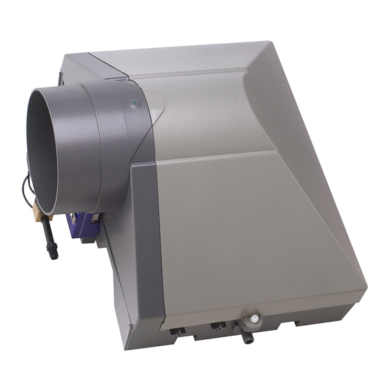
Figure 17
STEP #5: ELECTRICAL INSTALLATION
The humidistat supplied with the Model 5000 Humidifier can be
either duct or wall mounted. Duct mounting the humidistat is the
easiest installation. A wall mount provides more convenient control
of the humidifier and depending on your heating/ventilation
system may provide a more accurate indication of the relative
humidity level in your home. When wall mounting the humidistat
you should choose a central location (close to the furnace
thermostat) and you may be required to purchase extra low voltage
wire to run back to the humidifier. 20 ga will be sufficient.
DUCTING MOUNTING THE HUMIDISTAT
AND POWER CONNECTION TO THE HUMIDIFIER
The humidistat is packaged at the factory ready for wall
mounting. You will have to convert it to duct mounting. Refer to
fig. 18, when duct mounting the humidistat must be located
upstream (approx 6") from the humidifier or bypass tube on the
return duct. Select a convenient location to mount the humidistat
on the return duct. The unit comes with a humidistat mounting
template. THIS TEMPLATE IS FOR DUCT MOUNTING THE
HUMIDISTAT ONLY.
Humidistat
Base
Label
1. Drill the 4 marked humidistat mounting holes on the template
using the 5/64" drill bit (not supplied)
2. Using a 3/8" drill bit (not supplied) drill a hole inside the
rectangle marked Humidistat Cut Out.
5. YOU MUST RUN A
DRAINAGE TUBE FROM
THIS UNIT. Select a
convenient location for
running the 1/2" drainage
tube, 15 ft supplied.
Before you connect the
tubing to the drain fitting
on the bottom of the
unit, slip the 1/2" hose
clamp (supplied) over the
tubing (fig 17). Push the
tubing over the fitting and
secure in place with the
hose clamp.
CAUTION: Drain tubing
must not kink or come
into contact with sharp
edges or hot surfaces.
Low Voltage
Wire
Figure 18
3. Using the 3/8" hole drilled in step 2 as a starting point cut out
the Humidistat Cut Out area using tin snips (not supplied)
4. Locate the humidifier terminal panel on the side of the
humidifier cabinet, behind the bypass tube. Connect the two
ends of the transformer lead wires to the humidifier terminals
marked "24 VAC IN". (fig 19)
Figure 19
8. Remove the humidistat control from the base plate by undoing
the two screws holding it in place.
9. In the duct mounting application the base plate is used as the
front cover, reattach the humidistat control to the base plate
(fig 18).
10. Using the two 90-degree terminals included with the
humidistat kit, attach the two stripped wire ends of the
transformer leads that you cut in step 6 to the humidistat
terminals.
11. Mount the humidistat assembly into the duct cut out made in
step 3. Secure in place with four screws provided in the
humidistat kit (fig 17).
12. Remove the paper backing from the humidistat label and
apply onto the face plate. Install the knob onto the humidistat
control shaft.
Figure 20
WALL MOUNTING THE HUMIDISTAT
AND POWER CONNECTION TO THE HUMIDIFIER
CAUTION: When cutting or drilling in a wall take care not to hit
any of home's electrical or other utilities.
1. Select a central location in the home at eye level on an inside
wall. The best place is next to the furnace's thermostat.
2. Drill a small hole to fish low voltage wire (not supplied) out of
and leave approximately 6" of wire leads outside of the hole
for connection to the humidistat. Guide the other end of the
low voltage wire to the humidifier on the furnace.
3. Locate the humidifier terminal panel on the side of the
5. Run the transformer lead
wires from the humidifier to the
center of the hole you created
in step 3. Note the length of the
wire from the humidifier to this
point, and add approximately 2
more inches to this length. At
this point on the wire, carefully
cut the insulation between the
conductors and separate them
approx 3" (fig 20)
6. Cut on the conductors and
strip (approx 3/4") the insulation
from both ends (fig 21).
7. From the humidistat assembly
included with your unit remove
the humidistat. Gently pull off
the knob and label, and remove
the humidistat cover (fig 22 )
Figure 21