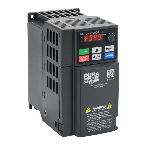
Automationdirect.com DURApulse GS10 Manuel de démarrage rapide - Page 2
Parcourez en ligne ou téléchargez le pdf Manuel de démarrage rapide pour {nom_de_la_catégorie} Automationdirect.com DURApulse GS10. Automationdirect.com DURApulse GS10 5 pages.

DURApulse GS10 AC Drive Quick-Start Guide
P02.00
External Terminal Control Circuits
STOP
REV
FWD
Setting value: 1
RUN
RUN
Two-wire operation control
FWD/DI1
FWD / STOP
REV / STOP
REV/DI2
DCM
Setting value: 2
Two-wire operation control
RUN / STOP
FWD / REV
Setting value: 3
Three-wire operation control
Specifications for Wiring Terminals – Control Circuit
GS10-xxxx All Models; All Frame Sizes
Terminal
Wire Gauge
24–18 AWG
Control
[0.21–0.82 mm
24–16 AWG
Relay
[0.21–1.31 mm
Control Terminal Distribution Diagram
Wiring Precautions
1) The RELAY terminal uses the PCB terminal block:
• Tighten the wiring with a 3.5 mm width and 0.6 mm thickness slotted screwdriver.
• The ideal length of stripped wire at the connection side is 9–10 mm.
• When wiring bare wires, make sure they are perfectly arranged to go through the wiring holes.
2) The control circuit terminal uses a spring clamp terminal block:
• Tighten the wiring with a 2.5 mm width and 0.4 mm thickness slotted screwdriver.
• The ideal length of stripped wire at the connection side is 9 mm.
GS10_QSP 1st Edition 06/15/2022
Recommended models or dimensions for ferrule terminals
Wire Gauge
Manufacturer
0.25 mm2
[24 AWG]
0.34 mm2
[22 AWG]
0.5 mm2
[20 AWG]
GS10
Specifications for Wiring Terminals – Main-Circuit Terminals
Notes:
FWD/DI1
• If installation environment temperature is greater than 45°C, please use copper wire with a 600V voltage
REV/DI2
rating and temperature resistance of 90°C or higher.
• For UL compliant installation, you must:
DCM
GS10
1) Use 75°C temperature resistant copper wire or better. Do not reduce wire gauge when using higher
temperature wire.
FWD/DI1
2) Use the specific ring lug part listed in the table below.
3) Use crimp tool CRIMPFOX 10S - 1212045 (Phoenix Contact) or DNT13-0101 (Dinkle).
DI3
REV/DI2
DCM
GS10
Torque
n/a (spring terminals)
2
]
5kg·cm
2
]
[4.3 lb·in]
Drive Models
GS11N-10P2
GS11N-10P5
GS11N-20P2
GS11N-20P5
GS13N-20P2
Control Terminal Location Map
GS13N-20P5
GS13N-21P0
GS13N-40P5
GS13N-41P0
GS11N-21P0
GS13N-22P0
GS13N-42P0
Model Name
A (MAX)
B (MAX)
D (MAX)
PHOENIX
AI 0,25- 8 YE
12.5
8
2.6
CONTACT
PHOENIX
AI 0,34- 8 TQ
12.5
8
3.3
CONTACT
PHOENIX
AI 0,5 - 8 WH
14
8
3.5
CONTACT
Max Wire
Min Wire
Torque
Screw
Ring Lug Dimensions (mm)
Gauge
Gauge
(±10%)
14AWG
[2.5 mm
2
]
Dimension
A
16AWG
B
[1.5 mm
2
]
C
9 kg-cm
14AWG
D
M3.5
[7.8 lb-in.]
[2.5 mm
2
]
18AWG
d2
[0.88 N·m]
[0.75 mm
2
]
E
F
16AWG
W
[1.5 mm
2
]
t
18AWG
[0.75 mm
2
]
Dimension
A
B
12AWG
[4 mm
2
]
C
15 kg-cm
12AWG
D
M4
[13.0 lb-in.]
[4 mm
2
]
d2
[1.47 N·m]
E
F
14AWG
W
[2.5 mm
]
2
t
Specifications for Wiring Terminals – Main-Circuit Terminals (continued)
Max Wire
Min Wire
W (MAX)
Drive Models
Gauge
Gauge
1.1
GS11N-11P0
1.3
8AWG
GS11N-22P0
[10 mm
1.4
GS11N-23P0
8AWG
10AWG
GS13N-23P0
[10 mm
2
]
[6 mm
8AWG
GS13N-25P0
[10 mm
14AWG
GS13N-43P0
[2.5 mm
12AWG
GS13N-45P0
[4 mm
8AWG
GS13N-27P5
[10 mm
8AWG
10AWG
GS13N-47P5
[10 mm
2
]
[6 mm
8AWG
GS13N-4010
[10 mm
Value
Min/Max
9.8
Max
3.2
Max
4.8
Min
4.1
Max
3.7
Min
13.0
Min
4.2
Min
6.6
Max
0.8
Max
Value
Min/Max
12.1
Max
3.6
Max
6.1
Min
5.6
Max
4.3
Min
13.0
Min
4.5
Min
7.2
Max
1
Max
GS10 AC Drive Quick-Start Guide – 1st Ed 06/15/2022
Torque
Screw
Ring Lug Dimensions (mm)
(±10%)
Dimension
Value
Min/Max
2
]
A
17.8
Max
B
5.0
Max
C
6.1
Min
20 kg-cm
D
7.2
Max
M4
[17.4 lb-in.]
2
]
d2
4.3
Min
[1.96 N·m]
E
13.0
Min
2
]
F
5.5
Min
W
10.5
Max
2
]
t
1.2
Max
2
]
Dimension
Value
Min/Max
2
]
A
17.8
Max
B
5.0
Max
C
6.1
Min
20 kg-cm
D
7.2
Max
M4
[17.4 lb-in.]
2
]
d2
4.3
Min
[1.96 N·m]
E
13.0
Min
F
5.5
Min
W
10.5
Max
2
]
t
1.2
Max
Page 2
