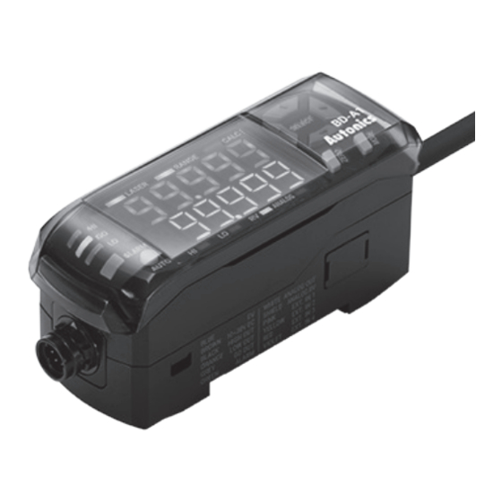
Autonics BD-A1 Manuel - Page 6
Parcourez en ligne ou téléchargez le pdf Manuel pour {nom_de_la_catégorie} Autonics BD-A1. Autonics BD-A1 14 pages. Laser displacement sensors amplifier unit
Également pour Autonics BD-A1 : Manuel du produit (3 pages)

-|Transparent setting
▣ Connections
▣ Control Output Diagram
◎ Judgment (High, Go, Low) and alarm output
Item
Inner circuit
NPN open
collector
Output short
output
over current
protection
circuit
Output short
over current
PNP open
protection
circuit
collector
output
▣ Installation Procedures
For optimum measurement, install the sensor head according to the following procedure.
Order Chapter
Check reference distance and
1
select mounting location
Check the precautions about
2
the measurement
Check mounting method and
3
mount
Check and apply the function
4
of amplifier unit.
guide|-
Item
Code color
Brown
Power
Blue
Black
Orange
Gray
Green
Output
White
Shield
Pink
Yellow
External
input
Red
Purple
Connection
(brown)+V
Load
(black)
OUT0
(orange)
OUT1
(gray)
OUT2
Max. 100mA
+
(green)
OUT3
30VDC
Load
-
(blue)GND
(brown)+V
+
Load
30VDC
-
(black)
OUT0
(orange)
OUT1
Max. 100mA
(gray)
OUT2
(green)
OUT3
Load
(blue)GND
Description
As the distance between the sensor head and the object approaches the reference
distance, accurate measurements can be made.
Refer to '▣ Mounting Location' to select optimum mounting location.
In case of measuring moving or rotating object, it is needed to install the sensor head
to correct direction.
When measuring at narrow area or concave object, it is needed to set the position of
the sensor head.
For the details, refer to '▣ Installation Precautions'.
Mount to the panel directly or through the enclosed bracket.
Refer to '▣ Mounting and Connecting Method' to mount the sensor head.
BD series support various settings and functions such as pitch light optimization,
zero adjustment setting, automatic sensitivity setting, calculation through the
amplifier unit.
Laser Displacement Sensor
Description
Power: 10-30VDC
Common GND (input, output, power)
HIGH Judgment
LOW Judgment
GO Judgment
Alarm
Analog: Following parameter value
(-5-5V, 0-5V, 1-5V, 4-20mA)
GND (Analog output)
※It is needed to distinguish from common GND.
External input 1
Select parameters as below and input a signal
External input 2
to execution.
(Timing, Output reset, Laser OFF,
External input 3
Zero adjustment, BankA, BankB, OFF)
External input 4
◎ Analog output
(-5-5V, 0-5V, 1-5V, 4-20mA)
White
-
mA
-
Shield
E-11
-11
