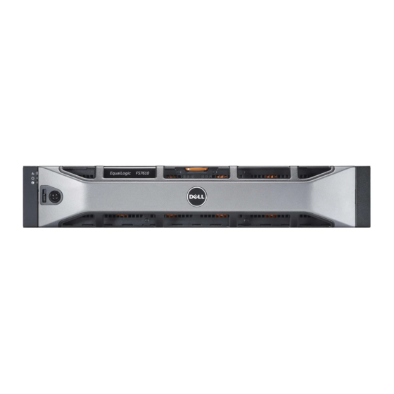
Dell EqualLogic FS7610 Manuel du propriétaire du matériel - Page 9
Parcourez en ligne ou téléchargez le pdf Manuel du propriétaire du matériel pour {nom_de_la_catégorie} Dell EqualLogic FS7610. Dell EqualLogic FS7610 32 pages. Appliances
Également pour Dell EqualLogic FS7610 : Vue d'ensemble (7 pages), Manuel d'installation et de configuration (46 pages)

Dell EqualLogic FS7610 Hardware Owner's Manual
Number Component
Service tag
1
Displays the appliance service tag information (identical to the service tag information on the front
panel).
Power supply (one of two)
2
Left: PSU1
3
Controller release latch
4
Controller handle
Controller (one of two); redundant NAS processing unit, each containing a backup power supply (BPS)
5
Left: Controller 1
Serial COM port (mini USB connector).
Allows you to connect a serial device to the system.
6
This connector is for service only. Use this connector only if asked to do so by Dell support.
7
USB port
8
Video port
From left to right: Service Action Button, Power-On Indicator/Power Button, Controller Health
9
Indicator, System Identification Button, and Cache Active/Off-Load LED (see
Remote KVM
10
LED Indicator/
Icon
Button
Service Action
Button
Controller State
Indicator/Power-On
Button
Table 3: FS7610 Back-Panel Components
Right: PSU2
Right: Controller 2
Table 4: Controller LED States and Descriptions
State and Description
Used for troubleshooting certain errors; press using the end of a paper clip.
Press and hold the button for 10 seconds to generate an SCI (System Control
Interrupt).
Use this button only if directed by qualified support personnel or after
consulting the operating system's documentation.
Controls the power supply to the appliance and indicates its state:
•
When the controller is ON, press and release to shut down.
•
When the controller is OFF, press and release to power the controller on.
Solid amber—The controller is ON and about to enter system power-on self-
test (POST). If the controller is ON but is not responding, the controller might
have a hardware failure that is not allowing it to start the BIOS POST.
Slowly blinking (flashes once every two seconds) amber—The controller is
currently in BIOS POST or option ROM load stage. If the controller is not
responding, it might indicate that a failure has occurred in either POST or
option ROM load phase.
Slowly blinking green (flashes once every two seconds)—The controller is
attempting to start the operating system. If the controller is not responding, slow
blinking green might indicate that the operating system did not load correctly.
Fast blinking green (flashes five times per second)—The controller is in
standby state waiting to be clustered.
1 Basic Appliance Information
Table
4).
3
