ALLNIC AUDIO A-2500 Manuel du propriétaire - Page 8
Parcourez en ligne ou téléchargez le pdf Manuel du propriétaire pour {nom_de_la_catégorie} ALLNIC AUDIO A-2500. ALLNIC AUDIO A-2500 14 pages. 211/845 single-ended triode monoblock power amplifiers

•
removed ALL the cushion materials (cardboard) from inside the tube chimneys.
leave the "O" rings on the small tubes; some prefer the sound with the O rings on.)
•
checked that all tubes are snug in their sockets
•
ensured the input connectors that you are using, single ended (RCA) or balanced (XLR), are firm and
secure and if using XLR, that the switch on the back of each chassis is set to the appropriate pin
configuration
•
securely and correctly fastened the speaker cables, ensured that they are also connected properly to
the speakers, and set the speaker impedance switch to match your speakers' impedance
•
turned on your source(s) and your preamplifier, and turned the preamplifier's volume control down to
zero or otherwise muted its output
Turn on the A-2500s by depressing the power switch button located (facing the front of the unit) on the
right side-panel (on one chassis and on the left side on the other) to the "on" position (See Figure 1). The
"on" position is with the top of the button switch depressed. Of course, the off position is the reverse.
After about a thirty to forty (30 - 40) second delay (the soft start), the A-2500s will be powered on. After
warm-up and application of full plate voltage, not all tubes may bias at the same rate. Allow one or two
minutes for all the tubes to reach full operating specification.
OPERATION
When the power is on, the current meter on the front of the chassis will illuminate (See Figure 3). From
this point on, operation is straight-forward. When you are finished listening, turn off your A-2500
monoblocks first; then, turn off your preamplifier and sources.
In the case of any failure, please contact Your Allnic dealer for assistance.
THE CURRENT METER
The illuminated meter indicates the current supply to the 211/845 power tube in the A-2500. There is a
screw-type potentiometer control on the chassis top in front of each 211/845.
When you turn on the A-2500s, the needle of the current meter should be centred between the two
parallel lines on the meter's face. Any error of current supply to or failure of a 211/845 tube is indicated by
the needle moving out from between these two parallel lines.
TUBES AND TUBE BIAS
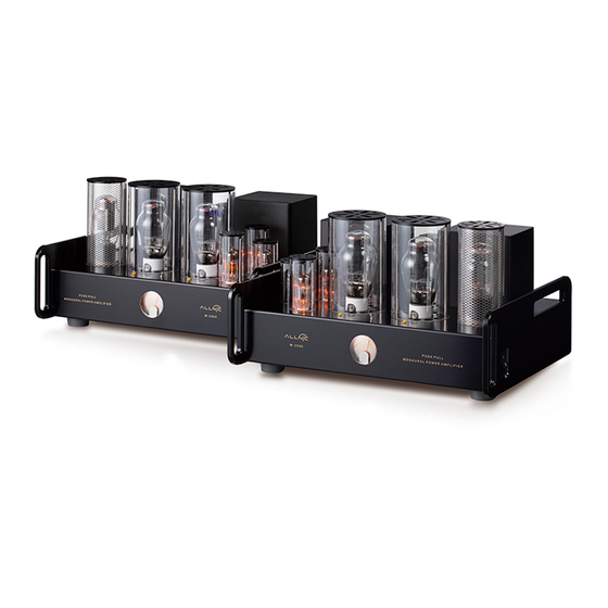
Each A-2500 monoblock uses the following tubes (See Figure 4)
BETWEEN 211/845 VERSIONS
• One (1) x 211 or 845 SET power tube
• One (1) x 6CM7 (211 power tube version)
• One (1) x 6DR7 (845 power tube version)
• One (1) x 5R4 rectifier tube
(except 5R4 rectifier):
TUBES ARE NOT INTERCHANGEABLE
8
(It is optional to
