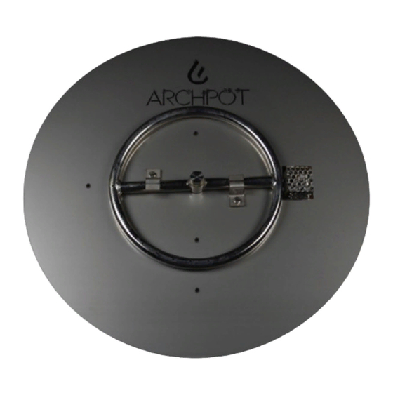
ARCHPOT 304 Manuel d'installation et d'utilisation - Page 6
Parcourez en ligne ou téléchargez le pdf Manuel d'installation et d'utilisation pour {nom_de_la_catégorie} ARCHPOT 304. ARCHPOT 304 12 pages. Apf burner system

3. The natural gas source line and low voltage A/C power must
be installed underground between each vessel, as shown in
Figure 2. The natural gas source line must be reduced to 1/2"
NPT for fire tables 42"+ and 3/8" NPT for fire vessels 24" - 36".
4. Using thread sealer, attach supplied flex line to natural gas
source line. Then attach the other end of the flex line to key
valve assembly as shown in photo. Do not kink or make a tight
radius bend on the gas hose.
5. Using thread sealer, attach the second supplied flex line to
the other side of the Key Valve Assembly making sure of proper
gas flow direction towards the burner.
6. Take the Completed Burner Assembly and attach the Yellow
and Blue wires from the AWEIS Control Module to the low
voltage A/C power source previously installed.
7. Using thread sealer, attach the flex line to the bottom of the
AWEIS Control Module.
8. Check all gas connections are tight, position the burner
assembly so that it sits level in the bowl. Rotate as required so
that the gas hose rests in a compact position.
Key Valve Assembly
(Inside View)
Key Valve Assembly
(Outside View)
6
