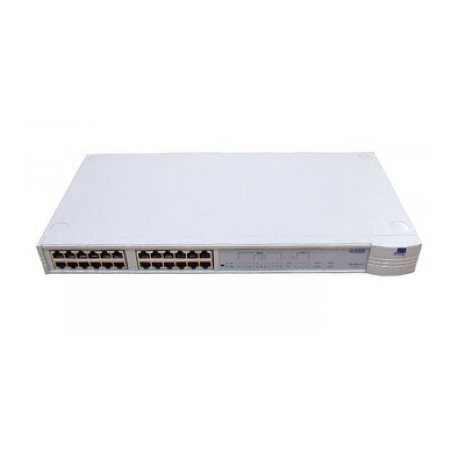
3Com SuperStack II 3C16592A Manuel de l'utilisateur - Page 3
Parcourez en ligne ou téléchargez le pdf Manuel de l'utilisateur pour {nom_de_la_catégorie} 3Com SuperStack II 3C16592A. 3Com SuperStack II 3C16592A 8 pages. Superstack ii baseline hubs and switches
Également pour 3Com SuperStack II 3C16592A : Fiche technique (12 pages)

3
Status LEDs
The Status LEDs show the state of a port and whether or not the
Link Pulse signal is present on the segment connected to a port:
Green
A 100 Mbps Link Pulse signal is being received and the
100BASE-TX segment attached to the port is functional.
Yellow
A 10 Mbps Link Pulse signal is being received and the
10BASE-T segment attached to the port is functional.
Flashing
The port has partitioned, due to an excessive number of
collisions, excessively long collisions, or a network loop.
To remove a network loop, examine your connections
and ensure that each piece of equipment is connected
to your network by only one connection.
Off
The Link Pulse signal is not being received. Either
nothing is connected to the port, or there is a problem:
Check that the attached device is powered on.
Check that the cable is the correct type and is not
faulty.
If the LED is off for port 12 or 24, check the setting of
the MDI switch. Refer to 2. Try toggling the MDI switch.
If you have connected different types of unit together,
check that your configuration conforms to the network
configuration rules for 10BASE-T and 100BASE-TX.
If the port is connected to another unit's MDI/MDIX
port, check the other unit's MDI switch position.
If these checks do not identify the cause of a problem, it may be
that the unit or the device connected to the port is faulty. Contact
your supplier for further advice.
4
Segment LEDs
The Segment LEDs indicate activity on the 10 Mbps and 100 Mbps
segments:
Flashing
Packets are being received or transmitted.
green
Flashing
Collisions are occurring on the segment. A low level of
yellow
collisions is a part of normal Ethernet and Fast Ethernet
operation. Excessive collisions may indicate a network
problem.
Off
No packets are being received or transmitted on the
segment.
5
Power LED
The Power LED indicates a number of conditions:
Green
The unit is powered on and ready for use.
Off
The unit is powered off.
If the power cable is connected correctly, there may be
a problem with the fuse within the power cord's plug.
If the unit appears to be operating and the LED is off,
contact your supplier.
Rear Panel Connections
6
Power Supply
The Baseline Dual Speed Hub automatically adjusts to the supply
voltage. Only use the power cord that is supplied with the Baseline
Dual Speed Hub, or a power cord of the same type and rating.
7
Socket for Redundant Power System
You can connect a 3Com SuperStack II Advanced Redundant Power
System (ARPS) (3C16071A) to the Hub. The ARPS is designed to
maintain the power to your Hub if a power supply failure occurs.
For normal redundancy, the ARPS requires one Type 1 Power Module
(part number 3C16072). For full redundancy, the unit requires two
Type 1 Power Modules combined using a Type 1 Y-Cable (part
number 3C16079). Contact your supplier for further details.
8
Self-adhesive Pads
The hub is supplied with six self-adhesive rubber pads: two reduced
height and four full height.
You do not need to apply the pads if you intend to rack
mount the unit.
If you are placing the units one on top of the other, you must use
the self-adhesive rubber pads supplied. Apply the pads to the
underside of each unit, sticking one in the marked area at each
corner. Place the units on top of each other, ensuring that the pads
of the upper unit line up with the recesses of the lower unit. Use the
two thinner pads when stacking the unit with a narrower one
above.
Positioning the Baseline Dual Speed Hub
!
CAUTION: When installing the Baseline Dual Speed Hub in
a stack of different size units, the Baseline Dual Speed Hub
!
must be installed above any larger units. Do not have a free
standing stack of more than six units.
When deciding where to position the Baseline Dual Speed Hub
ensure:
It is accessible and cables can be connected easily.
Cabling is away from:
Sources of electrical noise such as radios, transmitters and
broadband amplifiers.
Power lines and fluorescent lighting fixtures.
Water or moisture cannot enter the case of the unit.
Air flow around the unit and through the vents in the side of
the case is not restricted (3Com recommend that you provide
a minimum of 25 mm (1 in.) clearance).
To prolong the operational life of your units:
Never stack units more than six high if free standing, and
ensure that cables are supported so that they do not cause the
stack to fall over.
Do not place objects on top of any unit or stack.
Do not obstruct any vents at the sides of the case.
Rack Mounting
The Baseline Dual Speed Hub can be mounted in a 19-in. equipment
rack. Refer to the "Mounting Kit Instructions" section in this guide.
Power Up
Use the following sequence to power up the Baseline Dual Speed
Hub:
1
Check the network connections and cables.
2
Connect the power supply cable to the appropriate power
socket on the rear panel of the unit; refer to 6 or 7.
3
Connect the plug to the mains power supply outlet socket. If
you are using the Advanced Redundant Power System refer to
the ARPS User Guide.
When the Baseline Dual Speed Hub is powered on, the Power LED
should be lit. If it is not, refer to 5, "Power LED".
3
