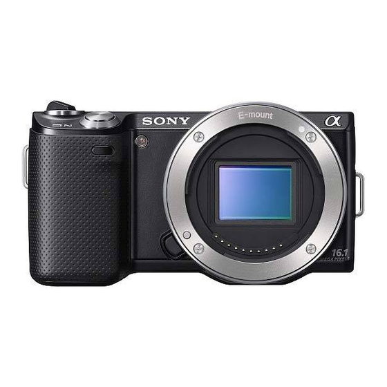
Sony NEX-5CK Manuel d'entretien - Page 11
Parcourez en ligne ou téléchargez le pdf Manuel d'entretien pour {nom_de_la_catégorie} Sony NEX-5CK. Sony NEX-5CK 34 pages. Interchangeable lens digital camera
Également pour Sony NEX-5CK : Manuel d'entretien (49 pages)

Ver.1.2 2010.07
The changed portions from
Ver.1.1 are shown in blue.
2-1-4. BT / RL SECTION
(NEX-5A/5D/5K/5CK/5H)
Imager Block Section
7�
161
(See Page 2-7)
(including CP001 (CMOS imager) and IS-077 complete board)
160
#200
9�
159
#202
(Note8)
158
8�
: BT900 (LITHIUM RECHARGEABLE BATTERY)
Board on the mount position.
(See page Level3 6-35)
Caution
Danger of explosion occurs if battery is incorrectly replaced. Replace only
with the same or equivalent type. Dispose of used batteries according
to the instructions.
Ref. No.
Part No.
Description
151
4-186-554-01
COVER, HDMI (BLACK)
151
4-186-554-11
COVER, HDMI (SILVER)
152
4-186-553-01
COVER, USB (BLACK)
152
4-186-553-11
COVER, USB (SILVER)
153
4-186-557-01
COVER, SHOE (BLACK)
153
4-186-557-11
COVER, SHOE (SILVER)
154
4-186-551-02
BASE, JACK COVER (BLACK) (Note6)
154
4-186-551-12
BASE, JACK COVER (SILVER) (Note6)
* 155
4-186-446-01
LIGHT (MS), GUIDE,
* 156
4-186-444-01
BASE, BT LID
157
A-1782-438-A
RL BLOCK ASSY (SERVICE) (Note5)
* 158
4-186-473-01
HOLDER, SP
* 159
4-186-556-01
SCREW, TRIPOD
160
A-1782-432-A
CABINET FRONT BLOCK ASSY (SERVICE) (BLACK)
(including CP001 (CMOS imager) and IS-077 complete board) (Note7, 9)
160
A-1782-433-A
CABINET FRONT BLOCK ASSY (SERVICE) (SILVER)
(including CP001 (CMOS imager) and IS-077 complete board) (Note7, 9)
161
A-1774-556-A
BUTTON BLOCK ASSY, RL
NEX-3A/3D/3K/5A/5D/5K/5CK/5H_L2
A6CCCE74558B3E905AD2CEF677F08944E4F80AE9D638E1A7EC0B95815DA1F3ED
(Note7, 9)
BT901
162
164
(Note1)
MIC901 (Note3)
BT900 (Note4)
C N
- 4 3
9
Solder
#71
#191
165
Solder
166
#192
168
#27
157
167
(Note5)
156
5�
154
(Note6)
153
155
152
151
Caution
電池の交換は,正しく行わないと破裂する恐れがあります。電池を交
換する場合には必ず同じ型名の電池又は同等品と交換してください。
使用済み電池は,取扱指示に従って処分してください。
Ref. No.
Part No.
Description
162
1-880-965-11
BT-060 FLEXIBLE BOARD
163
X-2547-936-1
BT FRAME ASSY (Note2)
* 164
4-186-448-01
GASKET (MS) (Note1)
165
A-1773-791-A
CN-439 BOARD, COMPLETE
166
4-186-449-01
SHEET (CN FPC)
167
1-880-967-11
FP-1236 FLEXIBLE BOARD
* 168
4-186-447-01
INSULATING SHEET (MS)
169
4-186-568-01
INSULATING SHEET, LC CONNECTOR (Note10)
0 BT900
1-756-813-11
LITHIUM RECHARGEABLE BATTERY (Note4)
0 BT901
1-780-858-11
TERMINAL BOARD BATTERY
MIC901 1-542-757-61
MICROPHONE UNIT (Note3)
#27
2-662-396-11
SCREW (M1.4), NEW, TRUSTAR, P2
#71
3-208-537-01
0+Z M1.4X2 NEW TORASUTA
#191
4-188-735-01
SCREW (M1.7)
#192
4-188-736-01
SCREW (TP1.4), P2
#200
4-178-124-11
SPECIAL (M1.4 (D2.75)) (BLACK) (Note8)
#202
4-178-124-31
SPECIAL (M1.4 (D2.75)) (SILVER) (Note8)
DISASSEMBLY
1. Remove to numerical order (
#191 X 2
6
6�
#27 X 1 → #191 X 1
163
8
(Note2)
169
#191
(Note10)
Screw
#27: M1.4 X 2.0
(Black)
2-662-396-11
2.0
Note
Note1: Refer to "Assembly-12: Inserting Gasket (MS) (NEX-
5A/5D/5K/5CK/5H)" when you assemble.
Note2: Refer to "Assembly-13: Assemble BT Holder Block Assy
(NEX-5A/5D/5K/5CK/5H)" when you assemble.
Note3: Refer to "Assembly-14: Routing of Microphone Harness
(NEX-5A/5D/5K/5CK/5H)" when you assemble.
Note4: Refer to "Assembly-15: Lithium Rechargeable Battery putting
position" when you assemble.
Note5: Refer to "Assembly-16: Note when assembling RL Block Assy
(NEX-5A/5D/5K/5CK/5H)" when you assemble.
Note6: Refer to "Assembly-19: Note on Alignment of the Flexible
Board when assembling Jack Cover Base
(NEX-5A/5D/5K/5CK/5H)" when you assemble.
Note7:
Precautions for Replacement of Cabinet Front Block Assy (Service)
As Cabinet Front Block Assy (Service) may be damaged by static
electricity from its structure, handle it carefully like for the MOS IC.
In addition, ensure that the receiver is not covered with dusts nor
exposed to strong light.
Note8: Refer to "THE COMBINATION OF CABINET'S COLOR AND
SCREW (NEX-5A/5D/5K/5CK/5H)" on page 2-1 about the
combination of cabinet's color and screw.
Note9: Refer to "PRECAUTION ON REPLACING THE CABINET
FRONT" on page 1-1 when replacing Cabinet Front Block Assy
(Service).
Note10: Refer to "Assembly-33: LC Connector Insulating Sheet
putting position" when you assemble.
2-6
to
) in the left figure.
5
9
7
Back View
#191
9
Back View
#27
#191
#71: M1.4 X 2.0
#191: M1.7 X 3.5
#192:
M1.4 X 4.0 (Tapping)
(Red)
(Black)
(Black)
3-208-537-01
4-188-735-01
4-188-736-01
1.7
1.4
1.4
2.0
3.5
Note1: 組立時は "Assembly-12: Inserting Gasket (MS)
Note2: 組立時は "Assembly-13: Assemble BT Holder Block Assy (NEX-
Note3: 組立時は "Assembly-14: Routing of Microphone Harness
Note4: 組立時は "Assembly-15: Lithium Rechargeable Battery
Note5: 組立時は "Assembly-16: Note when assembling RL Block Assy
Note6: 組立時は "Assembly-19: Note on Alignment of the Flexible
Note7:
前キャビネットAssy (サービス) 交換時の注意
前キャビネットAssy (サービス) は構造上,静電気により破壊される
恐れがあるため,MOS ICと同様に注意して取り扱ってください。
また,受光部にはゴミの付着,および強い光がはいることのないよ
うに注意してください。
Note8: キャビネット色とネジの組合わせについては,2 - 1 ページ
Note9: 前キャビネットAssy (サービス) を交換する場合,1 - 1 ペー
Note10: 組立時は "Assembly-33: LC Connector Insulating Sheet put-
#192 X 1
Bottom View
#192
#200 / #202 X 1
Bottom View
#200
#202
#200:
M1.4 X 3.8
#202:
M1.4 X 3.8
(Black)
(Silver)
4-178-124-11
4-178-124-31
1.4
1.4
1.4
3.8
4.0
3.8
(NEX-5A/5D/5K/5CK/5H)" を参照してください。
5A/5D/5K/5CK/5H)" を参照してください。
(NEX-5A/5D/5K/5CK/5H)" を参照してください。
putting position" を参照してください。
(NEX-5A/5D/5K/5CK/5H)" を参照してください。
Board when assembling Jack Cover Base
(NEX-5A/5D/5K/5CK/5H)" を参照してください。
の "THE COMBINATION OF CABINET' S COLOR AND SCREW
(NEX-5A/5D/5K/5CK/5H)" を参照してください。
ジの "PRECAUTION ON REPLACING THE CABINET FRONT" を
参照してください。
ting position" を参照してください。
