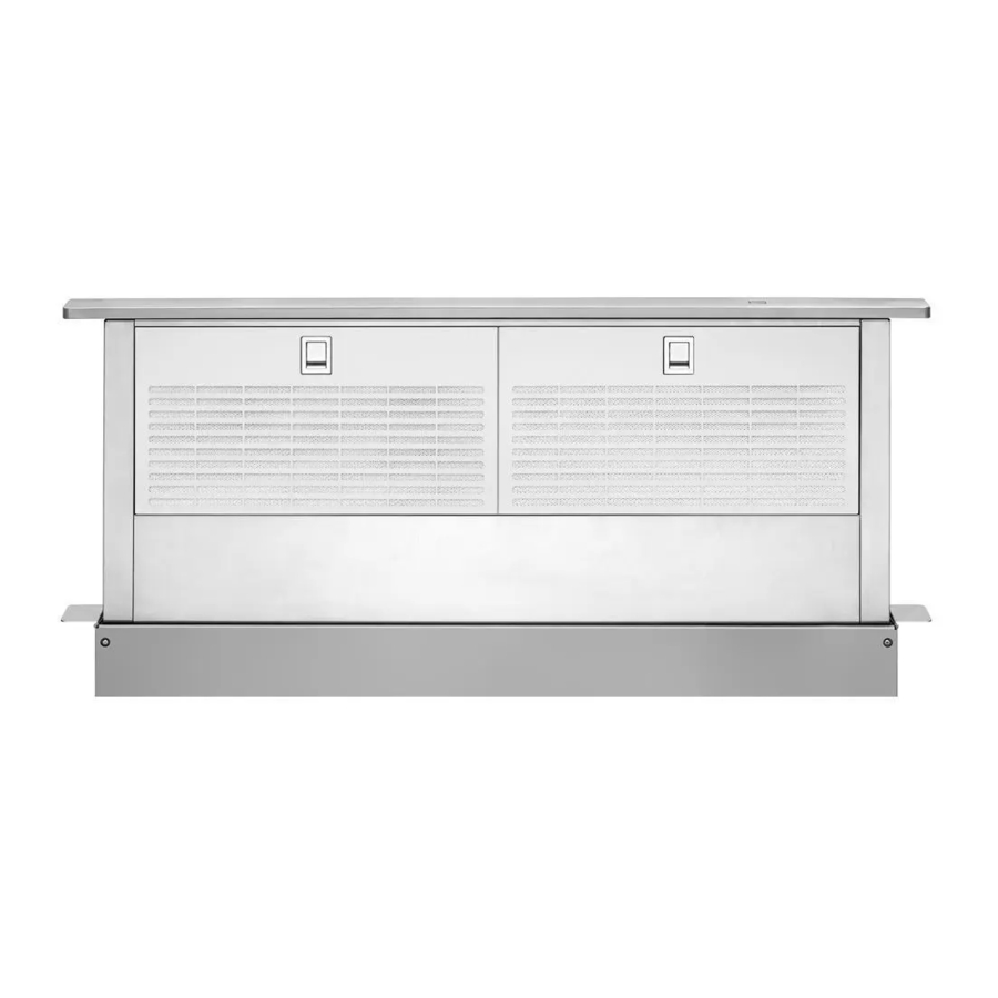
Whirlpool UXD8636DYS Instructions d'installation et manuel d'utilisation et d'entretien - Page 12
Parcourez en ligne ou téléchargez le pdf Instructions d'installation et manuel d'utilisation et d'entretien pour {nom_de_la_catégorie} Whirlpool UXD8636DYS. Whirlpool UXD8636DYS 36 pages. 30 76.2 cm and 36 91.4 cm retractable pop-up downdraft vent system
Également pour Whirlpool UXD8636DYS : Installation Instructions d'utilisation et d'entretien (40 pages)

4. Lift the ¼" (6.4 mm) deep cover off the shoulder screws in the
keyhole slots and set the cover aside.
5. Remove the screws from the wire mounting plate.
A
B
A. Screws
B. Wire mounting plate
C. Blower motor box
6. Hold the wire mounting plate and push the grommet out of
the mounting plate.
A. Wire mounting plate
B. Grommet
7. Slide the wire assembly through the slot in the wire mounting
plate to remove it.
8. Place the wire assembly through the opening to the opposite
side of the vent box.
9. Reassemble the wire assembly and grommet to the wire
mounting plate.
10. Install the wire mounting plate to the vent box using the
4 screws previously removed.
11. Place the blower motor box assembly with the keyhole slots
over the 2 shoulder screws on the rear of the vent box and
reconnect the wire connection to the blower motor.
12. Mount the blower motor box to the vent box and secure using
the 6 screws previously removed.
13. Mount the 4³⁄₄" (12.0 cm) cover box (supplied) to the front of
the vent box. Place the keyhole slots over the 2 shoulder
screws, align the mounting holes, and secure the cover box
to vent box using the 6 screws previously removed from the
¼" (6.4 mm) deep cover.
14. Go to the "Complete Installation" section.
12
A
C
A
B
Complete Installation
NOTE: The downdraft vent system is supplied with a 3¹⁄₄" x 10"
(8.3 x 25.4 cm) back draft damper and a 6" (15.2 cm) round vent
transition with damper. Refer to "3¹⁄₄" x 10" (8.3 x 25.4 cm) back
draft damper" or "6" (15.2 cm) round vent transition with
damper," depending upon the type of venting you are using.
3¹⁄₄" x 10" (8.3 x 25.4 cm) Back Draft Damper
1. Attach the 3¼" x 10" (8.3 x 25.4 cm) back draft damper to the
vent opening in the blower motor box, using three
3.5 x 9.5 mm screws.
B
A. 3.5 x 9.5 mm screws
B. 3¼" x 10" (8.3 x 25.4 cm) back draft damper
6" (15.2 cm) Round Vent Transition With Damper
1. Attach the 6" (15.2 cm) round vent transition to vent opening
(left or right side venting only is recommended), using two
3.5 x 9.5 mm screws.
A
B
A. 3.5 x 9.5 mm screws
B. 6" (15.2 cm) round vent transition with damper
A
A
