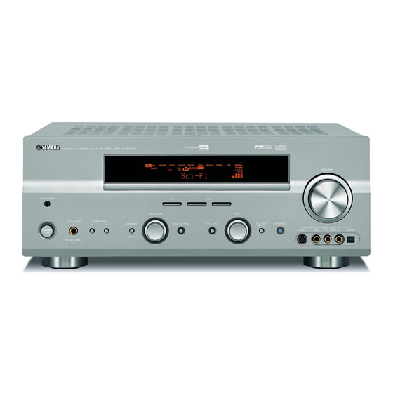
Yamaha DSP-AX757 Manuel d'entretien - Page 42
Parcourez en ligne ou téléchargez le pdf Manuel d'entretien pour {nom_de_la_catégorie} Yamaha DSP-AX757. Yamaha DSP-AX757 49 pages. Av receiver/av amplifier

A
B
C
SCHEMATIC DIAGRAM (OPERATION)
1
2
~
~
-19.3
-28.8
~
~
3
~
-21.2
~
~
4.9
-21.4
~
-26.9
-8.2
-26.8
-19.3
4.9
4.9
-26.9
-26.9
-26.9
-26.9
4
-26.9
-26.8
5
5.0
0
5.0
6
7
8
IC801 : M66003-0131FP
9
FL Display Driver
CS
2
SCK
3
SDATA
4
XIN
7
XOUT
6
10
RESET
1
Vcc1
8
Vcc2
18
Vss
5
Vp
64
D
E
F
HTR-5860
4.9
-19.5
-21.4
~
-25.0
-19.5
-23.2
~
DISPLAY DRIVER
~
-15.4
-19.5
4.9
4.9
2.2
2.2
-21.3
0
4.9
-21.2
4.9
4.9
4.9
Page 86
F-1
HTR-5860 Page 93
H-8
TO SUBTRANS (2) CB456
Display code
RAM
CGROM
44
SEG00
(8-bit x 60)
(35 bit x 166)
Segment
19
SEG25
Code
output
write
17
SEG26
circuit
CGROM
Serial
dot data
9
SEG34
data
(35 bit x 16)
write
receive
Code/
circuit
command
45
SEG35
control
circuit
DIG11/
52
SEG42
DIG12/
51
SEG41
code
Segment
DIG13/
50
select
SEG40
digit
select/
DIG14/
49
Clock
output
SEG39
timing
Display
generator
clock
controller
scan pulse
circuit
DIG15/
48
SEG38
DIG16/
47
SEG37
DIG17/
46
SEG36
63
DIG00
Digit
output
circuit
53
DIG10
G
H
-22.0
-22.0
5.1
0
4.9
-19.5
-19.4
-22.3
-25.6
-25.6
4.9
-29.0
-21.4
-21.4
0
0
0
0
0
0
TO DSP CB7
Page 87
I-4
TO FUNCTION (1) CB309
I
J
K
5
4.9
1
0.2
3
0
2
4
0.2
0
0
4.9
0
0
0
0
Page 87
0
0
0
0
OPTIMIZER MIC AMP
5.1
0
11.9
0
0
0
0.7
0
0
0
10.7
-12.0
0
0
IC901 : µPC4570G2
IC881 : SN74AHCT1G32DCKR
Single 2 Input OR
Dual OP-Amp
A
1
5
VCC
OUT
1
8
+V
1
CC
B
2
–IN
1
2
7
OUT
2
GND
3
4
Y
+
–
+
–
+IN
1
3
6
–IN
2
–V
CC
4
5
+IN
2
L
M
N
RX-V757/DSP-AX757/DSP-AX757SE
RX-V657/HTR-5860
G-1
TO FUNCTION (1) CB306
4.2
5.4
* All voltages are measured with a 10M Ω /V DC electronic volt meter.
* Components having special characteristics are marked Z and
must be replaced with parts having specifications equal to
those originally installed.
* Schematic diagram is subject to change without notice.
* 電圧は、内部抵抗10MΩの電圧計で測定したものです。
* Z印のある部品は、安全性確保部品を示しています。部品の交換が必要な場合、
パーツリストに記載されている部品を使用してください。
* 本回路図は、標準回路図です。改良のため予告なく変更することがございます。
89
