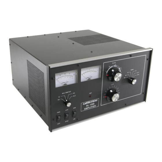
AMERITRON AL-1500 Buku Petunjuk - Halaman 9
Jelajahi secara online atau unduh pdf Buku Petunjuk untuk Penguat AMERITRON AL-1500. AMERITRON AL-1500 16 halaman. Full power linear amplifier

LOCATION
-Do not operate the Amplifier in excessively warm locations
or near heating vents or radiators. Be sure air can circulate
freely around and through the Amplifier cabinet. Provide an
unobstructed air inlet for the blower. Do NOT place anything
that will impede the free flow of air within 2 inches of the
cabinet ventilation holes.
VENTILATION
The AL-1500 ventilation system has been designed and
tested to maintain tube seal temperature safely below the
tube manufacturer's rating at 1500 watts output with a 100%
duty cycle when properly tuned. The blower in the AL-1500
is a permanently lubricated type that requires no main-
tainence in normal operation. To insure proper ventilation in
your installation, observe the following:
1. Do not block or unduly restrict the ventilation holes in
the cover. Be sure that the amplifier is located in an area
so the vent holes have open air circulation.
2. The exhaust air flow is over 30 CFM. Do not "assist" the
air flow unless the fan exceeds the AL-1500 blower
CFM by a factor of 2:1.
3. Do not mount additional fans on the AL-1500 cabinet.
4. The exhaust air will become quite warm at higher power
levels. Do not place any heat sensitive objects in the
exhaust air stream.
Proper tuning of a grounded grid linear amplifier is best
accomplished with an understanding of what each control
does and what the meters are telling the operator about the
condition of TUNE.
The tuning controls function as follows:
PLATE: This control tunes the amplifier output circuit to the
operating frequency. It should always be adjusted for
maximum output power or maximum grid current. Due to
interaction with the ''LOAD" control, a "touch-up" should be
performed after any load adjustments.
LOAD: This control adjusts the coupling of amplifier to the
antenna or load. It should be adjusted to keep the grid
current in the proper operating range. As the loading
capacitance is reduced (by rotating the control to a higher
front panel number), the coupling is increased. An increase
in coupling will reduce grid current and increase the amount
of drive the amplifier will accept without component
damage.
A common mistake in tuning is to adjust the "LOAD"
control at low drive powers and apply more drive dur
INSTALLATION Cont.
POWER CONNECTIONS
The AL-1500 is supplied with a NEMA 6-15P plug for 240V
AC operation. Operation with power main voltages below
200 volt is not recommended. Special transformers are re-
quired for 200V, 50/60 Hz operation (see NOTE on page 1).
Refer to the "Transformer Installation" section on pages 4
and 5 for the correct wiring for 220 to 240 volt operation.
NEVER REWIRE THE POWER SUPPLY TO BOOST
THE HIGH VOLTAGE ABOVE 3700 VOLTS.
The wiring between the fuse box and the amplifier AC outlet
must be No. 12 gauge or larger in order to supply the current
required (13 amperes) without a significant drop in the line
voltage. The outlet should be fused for 20 amperes.
GROUNDING
Connect a good RF and earth or water pipe ground to the
ground post on the rear panel of the Amplifier. Use the
heaviest and shortest connection possible.
Before you use a water pipe ground, inspect the connections
around the water meter and make sure that no plastic or rub-
ber hose connections are used. These connections interrupt
electrical continuity to the water supply line. Install a jumper
around any insulating water connections you may find. Use
heavy copper wire and pipe clamps. It is best to ground all
equipment to one point at the operating position and then
ground this point as described above.
TUNING INSTRUCTIONS
ing operation. Excessive grid current, distortion on SSB or
arcing in the tank components occurs when full drive power
is applied to the amplifier without the "LOAD"' set for
enough clockwise (higher loading).
It is important to remember the loading must be set properly
for the PEAK power the amplifier is expected to develop. 50
watts PEP will be the maximum drive the amplifier will
safely handle if the output of the amplifier is tuned with 50
watts of carrier drive. Any attempt to go beyond the amount
of drive power the amplifier was originally tuned at will
result in a rapid increase in grid current, splatter and even
damage to components.
The "LOAD" control should be adjusted for maximum
output power without exceeding the recommended grid
current. DO NOT USE THE LOAD CONTROL TO
REDUCE POWER IN A GROUNDED GRID AMPLIFIER.
The drive from the exciter should be reduced if the amplifier
plate current or output power is excessive. The "LOAD"
setting should be increased if grid current is excessive. Any
errors in adjusting this control should be made in favor of a
higher load setting (clockwise).
