Gage Bilt GB568 Manual Petunjuk Asli - Halaman 11
Jelajahi secara online atau unduh pdf Manual Petunjuk Asli untuk Alat Keling Gage Bilt GB568. Gage Bilt GB568 20 halaman. Installation tool
Juga untuk Gage Bilt GB568: Manual Petunjuk Asli (16 halaman)
WARNING:
Do not cycle tool without air bleeder assembly (704153), or the screw and stat-o-seal, installed in tool head. Severe
personal injury could result.
WARNING:
Use CAUTION when removing screws or the air bleeder assembly (704153). Hydraulic oil may be under pressure.
CAUTION:
Before filling handle assembly (722132), air piston assembly (704121) must be all the way down.
CAUTION:
When forcing piston rod assembly (722133) downward, with head cylinder (568108) removed, hydraulic oil will eject
forcibly from tool.
CAUTION:
When bleeding tool, ensure tubing is free from kinks or other obstructions.
Note:
•
Air Bleeder Assembly (704153) (sold separately) is required.
BLEEDING PROCEDURE:
1. To replace a small amount of oil,
cylinder (568108) upward and lay flat on a table or bench. When bleeding tool always keep the head cylinder (568108) higher than
the handle assembly (722132).
2. Remove nose assembly, button head cap screw (402482) and stat-o-seal (S572) from manifold handle (744303-1) hole marked "3".
3. Install air bleeder assembly (704153) and connect tool to air line. Cycle ten times holding actuator (704130) down for 2-3 seconds
between cycles to re-move any air from the tool.
reinstall button head cap screw (402482) and stat-o-seal (S572) on from manifold handle (744303-1). Torque 35-40 inch lbs. (3.95 - 4.52 Nm).
Do not over tighten.
4. Remove button head cap screw (402482) and stat-o-seal (S572) from swivel adapter (568121).
5. Install air bleeder assembly (704153) and connect tool to air line. Cycle tool ten times holding actuator (704130) down for 2-3 seconds
between cycles to re-move any air from the tool.
reinstall button head cap screw (402482) and stat-o-seal (S572) on from manifold handle (744303-1). Torque 35-40 inch lbs. (3.95 - 4.52 Nm)
Do not over tighten. This will ensure the removal of any air from the hydraulic system and is replaced with oil.
FILLING PROCEDURE: (required after tool has been dismantled)
1. Place piston rod wrench assembly (704149) in power cylinder (722134) and carefully push piston rod assembly (722133) and air
piston assembly (704121) completely down.
2. Fill handle assembly (722132), power cylinder (722134) and the oil passage on top of handle assembly (722132) with automatic
transmission oil, Dexron® III or equivalent. When looking at the top of the handle assembly (722132), the oil passage is the hole
that is counterbored for o'ring (S832). See image below.
3. Attach manifold handle (744303-1) to handle assembly (722132) ensuring gasket (704129) and o'ring (S832) are properly installed.
Apply Loctite® 242 to button head cap screws (A-928) and torque uniformly to 40 inch lbs. (4.52 Nm) to prevent leakage around
gasket (704129).
4. Coil tool hoses up on bench and lay handle assembly (722132) down on side so that the hole marked #4 on manifold handle (744303-1)
is to the top. Set swivel adapter (568121) over a small bucket or can. Completely fill up fill bottle (745263). Remove button head cap
screw (402482) and stat-o-seal (S572) from both swivel adapter (568121) and manifold handle (744303-1) hole marked "4".
5. Attach fill bottle (745263) to manifold handle (744303-1) hole marked "4" and in one continuous squeeze force oil into manifold-
handle (744303-1) until oil starts to flow from bleeder hole on swivel adapter (568121). While still squeezing the fill bottle (745263),
use other hand to replace button head cap screw (402482) and stat-o-seal (S572) on swivel adapter (568121) and torque to 35-40
inch lbs. (3.95 - 4.52 Nm). Do not over tighten. This may require two people.
6. Proceed to bleeding procedure above to remove any air from hydraulic system.
Oil Passage hole
O'ring (S832)
***Keep air
hole free
from oil***
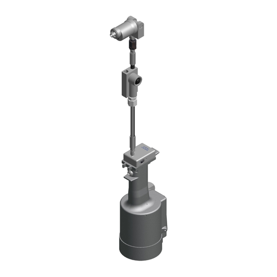
GB722/568 INSTALATION TOOL
FILLING AND BLEEDING PROCEDURE:
DISCONNECT AIR FROM TOOL.
DISCONNECT AIR FROM TOOL,
DISCONNECT AIR FROM TOOL,
Handle Assy and
Power Cylinder hole
Images may not reflect actual tool.
Stand handle assembly (722132) on floor, stretch hose and head
Hole marked #3 on
Manifold Handle (744303)
11
remove the air bleeder assembly (704153) and
remove the air bleeder assembly (704153) and
Swivel Adapter (568121)
bleed screw
11/21 REV. 5/22