Gage Bilt GB808 Manual Petunjuk Asli - Halaman 12
Jelajahi secara online atau unduh pdf Manual Petunjuk Asli untuk Generator Portabel Gage Bilt GB808. Gage Bilt GB808 20 halaman.
WARNING:
Only qualified and trained personnel shall perform overhaul.
WARNING:
Personnel must read and understand all warnings and cautions.
WARNING:
Tool must be maintained in a safe working condition at all times and examined on a daily basis for damage or
wear. Any repair must be done by qualified personnel trained on Gage Bilt procedures.
WARNING:
Disconnect tool from its power source before performing overhaul. Severe personal injury may occur if power
source is not disconnected.
WARNING:
Excessive contact with hydraulic oil and lubricants must be avoided (See safety data sheet documents for all
applicable materials
WARNING:
When operating, repairing or overhauling tool, wear approved eye protection. Do not look in front of tool or
rear of tool when installing fastener.
WARNING:
Use only Gage Bilt hydraulic hoses and couplings, or equivalent, rated for 10,000 psi. (689.5 bar) working pressure.
WARNING:
Ensure air hose is securely connected to avoid possible hose whipping (Air Actuated Tools only).
Note:
•
Dispose of hydraulic oil in accordance with manufacture safety datasheet.
•
All tool materials are recyclable except rubber o'rings, seals and wipers.
•
SERVICE KIT (808020), which contains a complete set of o'rings, back-up rings and screws, can achieve a complete
overhaul.
If a tool is performing poorly or leaking, a complete overhaul may be necessary.
Perform overhaul in a clean, well lit area using care not to scratch or nick any smooth surface that comes in contact with an o'ring.
Use of Lubriplate® #630-AA (Gage Bilt part no. 402723) during reassembly to prevent tearing or distorting of o'rings.
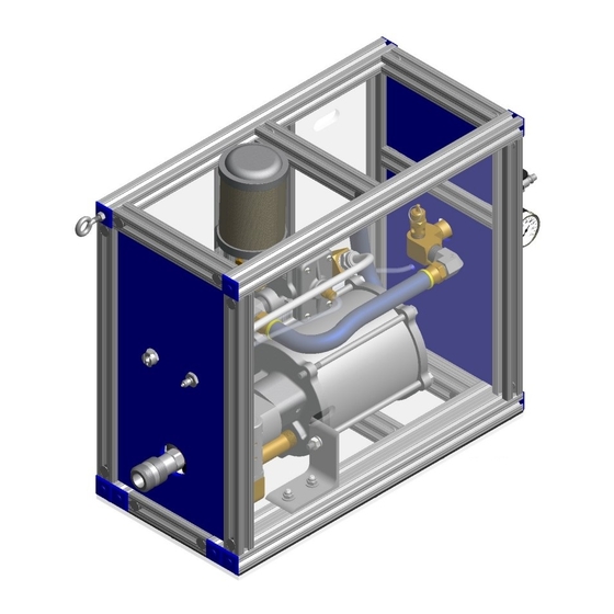
1. Take picture of the booster assembly (808009) for reference when re-assembling.
2. Disconnect hose assemblies (808105 & 808106) connected to booster assembly (808009).
3. Disconnect air line (808023) from elbow (A-1077). (See pg. 14 Quick Exhaust Valve).
4. Loosen and remove (2X) hex nuts (400216) & (2X) split lock washers (400182) from mounting brackets (808049 & 808050) then
carefully remove booster assembly (808009). (See pg. 13).
5. Remove five hex bolts (2X) (407708) & (3X) (407710) and disassemble. (See parts lists pg. 13).
6. Replace o'rings and polyseals (4X) 400826, (2X) 404228, (3X) 407694 & 407693. (See parts lists pg. 13).
7. Reassemble booster assembly (808009). Apply thread sealant (if required) to all necessary fittings. (See hydraulic thread preparation).
8. Torque three hex bolts (407710) to 20-25 ft lbs. (27-34 Nm) and two hex bolts (407708) 12-15 ft. lbs. (16.3 - 20.3 Nm) (See parts lists pg. 13).
9. Secure booster assembly (808009) to mounting brackets (808049 & 808050) and reattach all hose assemblies. (See parts lists pgs.
14 & 15).
10. Bleed tool and booster assembly (808009) per bleeding procedure (See pg 11).
An oil pan assembly (808148) with a drain plug (button head cap screw (402482) & stat-o-seal (S572) and gasket oil-pan (808147) is attached
to this powerunit.
To drain oil pan:
1.
Place container under drain to collect oil.
2.
Place allen wrench into button head cap screw (402482) (drain plug) under powerunit.
3.
Using an allen wrench, loosen and remove the button head cap screw (402482) and stat-o-seal (S572) letting the hydraulic oil
drain from the hole into an approved container. It may be necessary to tilt the powerunit to remove all hydraulic oil. Dispose of oil in
accordance with the manufacture safety data sheet.
4.
Wipe oil pan (808146) and any related parts down with a clean dry rag and dispose of accordingly.
Drain all hydraulic oil and dispose of oil in accordance with manufacture safety datasheet. All tool materials are recyclable except
plastic panels and rubber o'rings, seals, wipers and hoses.
GB808 POWERUNIT
OVERHAUL BOOSTER ASSEMBLY
).
OIL PAN
TOOL DISPOSAL
12
12/21 REV 4/22