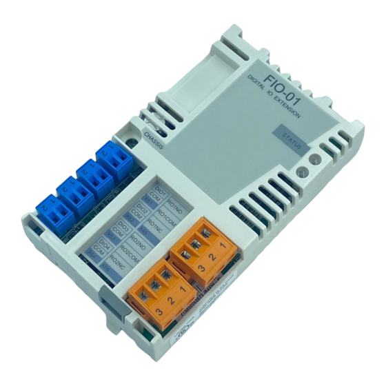
ABB FIO-01 Panduan Cepat - Halaman 4
Jelajahi secara online atau unduh pdf Panduan Cepat untuk Peralatan Industri ABB FIO-01. ABB FIO-01 14 halaman. Digital i/o extension
Juga untuk ABB FIO-01: Panduan Memulai Cepat (12 halaman)

4
If you need to remove the adapter module after it has been installed into
the drive, use a suitable tool (e.g. small pliers) to carefully pull out the
locking tab. Then loosen the screw and pull out the module.
Note: The screw tightens the connections and grounds the module. It is
essential for fulfilling the EMC requirements and for proper operation of
the module.
Terminal designations
Marking
X61, X62, X63,
X64
1
2
X65, X66
1
2
3
Wiring
Use max. 1.5 mm
conductors for the relay outputs. Ground the cable shield at the drive
end to a signal ground terminal. Refer to hardware manual of the drive or
unit for more information.
Do not route signal cables parallel to power cables.
Tighten the digital I/O signal wiring to 0.3 N·m and the relay output
wiring to 0.5 N·m.
Quick guide - FIO-01
Description
Digital inputs or outputs. Drive parameters
select signal type and use in control
program.
DIOx
• Input: 24 V, "0" < 5 V, "1">15 V.
COM
• Output: Current sink is 500 mA. If more
than two digital outputs are used, current
source is 25 mA. Otherwise current source
is 50 mA.
ROxNO
ROxCOM
ROxNC
2
conductors for the digital signals and max. 2.5 mm
Relay outputs:
• max. 240 VAC, 2 A resistive load
• max. 30 VDC, 5 A resistive load
Inbuilt varistors for inductive load
protection.
2
