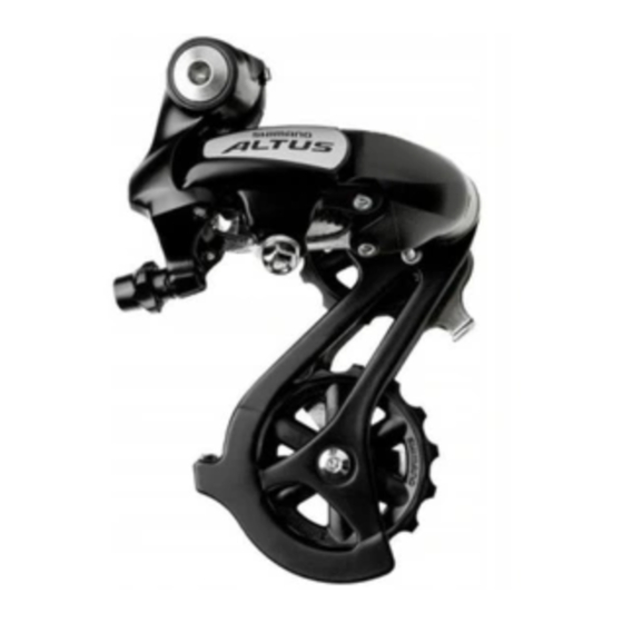
Shimano CS-HG50-8I Manual - Halaman 4
Jelajahi secara online atau unduh pdf Manual untuk Aksesori Sepeda Shimano CS-HG50-8I. Shimano CS-HG50-8I 5 halaman. Rear drive system

SIS Adjustment
1. Top adjustment
Turn the top adjustment screw to adjust
so that the guide pulley is in line with the
outer line of the smallest sprocket when
looking from the rear.
2. Connecting and securing the inner cable
Operate lever (B) at least 7 times to set the
lever to the highest position.
Remove the screw, and then remove the cover.
Pull out the inner cable as shown in Figure ,
and then install the new inner cable.
Tightening torque :
0.3 - 0.5 N·m {3 - 4 in. lbs.}
Connect the cable to the
rear derailleur and, after
taking up the initial slack in
the cable, re-secure to the
rear derailleur as shown in
the illustration.
Tightening torque :
5 - 7 N·m {44 - 60 in. lbs.}
Inserting the inner cable
Insert the inner cable into the outer casing from the end with the marking on it.
Apply grease from the end with the marking in order to
maintain cable operating efficiency.
Cutting the outer casing
When cutting the outer casing, cut the opposite end to
the end with the marking. After cutting the outer casing,
make the end round so that the inside of the hole has a
uniform diameter.diameter.
Attach the same outer end cap to the
cut end of the outer casing.
3. Low adjustment
Turn the low adjustment screw so
that the guide pulley moves to a
position directly in line with the
largest sprocket.
4. How to use the B-tension adjustment screw
Mount the chain on the smallest chainring
and the largest sprocket, and turn the
crank arm backward. Then turn the B-
tension adjustment screw to adjust the
guide pulley as close to the sprocket as
possible but not so close that it touches.
Next, set the chain to the smallest
sprocket and repeat the above to make
sure that the pulley does not touch the
sprocket.
1
2
Guide pulley
Cover
Inner cable
Note: Be sure that the cable is
securely in the groove.
Pull
Outer end cap
Largest sprocket
Guide pulley
2
1
Largest sprocket
Smallest sprocket
2
2
1
1
Outer line of
smallest sprocket
1
2
Low adjustment
screw
Screw
Lever (B)
Groove
Marking
1
2
Low adjustment
screw
1
2
B-tension
adjustment screw
