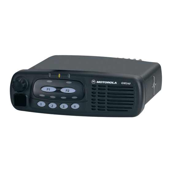
Motorola GM340 Informasi Layanan - Halaman 15
Jelajahi secara online atau unduh pdf Informasi Layanan untuk Radio Motorola GM340. Motorola GM340 32 halaman. Gm series professional radio uhf (403-470mhz)
Juga untuk Motorola GM340: Panduan Pengguna (32 halaman), Informasi Layanan (34 halaman), Informasi Layanan (32 halaman)

Controlhead Model for GM380, and GM1280
prevents radio circuitry from discharging this capacitor. The +5V at the second anode of D0855
speeds up charging of C0856, when the host radio is turned on by a high level at the ignition input
while the supply voltage is applied to the radio. This prevents the microprocessor from accidently
entering bootstrap mode.
4.3
Power On / Off
The On/Off/Volume knob when pressed switches the radio's and the controlhead's voltage regulators
on by connecting line ON OFF CONTROL to line UNSW 5V via D0852. Additionally, 5 volts at the
base of digital transistor Q0853 informs the controlhead's microprocessor about the pressed knob.
The microprocessor asserts pin 8 and line CH REQUEST low to hold line ON OFF CONTROL at 5
volts via Q0852 and D0852. The high line ON OFF CONTROL also informs the host radio, that the
controlhead's microprocessor wants to send data via SBEP bus. When the radio returns a data
request message, the microprocessor will inform the radio about the pressed knob. If the radio was
switched off, the radio's µP will switch it on and vice versa. If the On/Off/Volume knob is pressed
while the radio is on, the software detects a low state on line ON OFF SENSE, the radio is alerted via
line ON OFF CONTROL and sends a data request message. The controlhead µP will inform the
radio about the pressed knob and the radio's µP will switch the radio off. If the radio is switched on
either manually or automatically it's +5V source switches on the controlhead's voltage regulator
U0861 via line 5 SOURCE and transistor Q0866 and the controlhead's microprocessor starts
execution.
4.4
Microprocessor Circuit
The controlheadcontrolhead uses the Motorola 68HC11K4 microprocessor (uP) (U0871) to control
the LED's and the LCD and to communicate with the host radio. RAM and ROM are contained within
the microprocessor itself.
The microprocessor generates it's clock using the oscillator inside the microprocessor along with a 8
MHz ceramic resonator (U0873) and R0873.
The microprocessor's RAM is always powered to maintain parameters such as the last operating
mode. This is achieved by maintaining 5V at µP pin 76. Under normal conditions, when the radio is
off, USW 5V is formed by FLT A+ running to D0855. C0856 allows the battery voltage to be
disconnected for a couple of seconds without losing RAM parameters. Diode D0855 prevents radio
circuitry from discharging this capacitor.
There are 8 analogue to digital converter ports (A/D) on the µP. They are labeled within the device
block as PE0-PE7. These lines sense the voltage level ranging from 0 to 5V of the input line and
convert that level to a number ranging from 0 to 255 which can be read by the software to take
appropriate action.
Pin VRH is the high reference voltage for the A/D ports on the µP. If this voltage is lower than +5V the
A/D readings will be incorrect. Likewise pin VRL is the low reference for the A/D ports. This line is
normally tied to ground. If this line is not connected to ground, the A/D readings will be incorrect.
The microprocessor can determine the used keypad type by reading the level at port PE5.
Connections S0931 – S0935 are provided by the individual keypads.
The MODB / MODA input of the µP must be at a logic „1" for it to start executing correctly. The XIRQ
and the IRQ pins should also be at a logic „1".
4.5
SBEP Serial Interface
The host radio (master) communicates to the controlhead µP (slave) through its SBEP bus. This bus
uses only line BUS+ for data transfer. The line is bi-directional, meaning that either the radio or the
2-9
