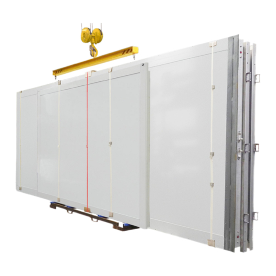
AluTeam BR 248-2 Manual Petunjuk Perakitan - Halaman 8
Jelajahi secara online atau unduh pdf Manual Petunjuk Perakitan untuk Truk AluTeam BR 248-2. AluTeam BR 248-2 12 halaman. Box body kits

1
2
3
F
max. 625 mm,
M 10 - 8.8
Series 248-2 Assembly Instructions
max. 450 mm,
Ø 6.5 mma
Distance from the wall 25 mm
Substructure bolting
instruction
3.5 Assembling the frame, doors, etc.
•
If the kits have a top gate, latch the gas springs of the gate onto the
ball heads. If the frame pillar does not have an integrated seal, the
gate must be secured against lateral movement during operation us-
ing two brackets as shown in the sketch.
•
If a kit includes rear doors, they must be closed to check the fit. If
necessary, adjust the rotary bar locks by adjusting the position of
the hitches. Always re-check the screws for tight fit.
•
In the case of kits with supplied roller shutter, the roller shutter
must be installed as described in the instructions supplied, "Installa-
tion of DP 25HR-d 2007". Rivet the guide rails onto the preassembled
horizontal top-hat sections.
3.6 Sealing
•
Use the bond-activating cleaner of the kit to clean the sealing
surfaces and after approx. 10 sec. flash-off time, treat with Sika
Activator 205.
After approx. 10 min. flash-off, seal with the sealing compound:
•
1
Front right and left roof corner, all round from above and the rivet
head.
2
The connection of the walls to the roof and the corner cover.
3
The connections of the top frame crossmember to the pillars.
The seals should only be pressed in and smoothened with
•
smoothing agent or water —without soap additives.
•
If necessary, the joint between the side door and the floor must also
be sealed.
3.7 Positioning on the underbody or chassis
•
Fasten the box body onto the substructure as shown in the sketch
on the left.
Attention:
Failing to follow the bolting instruction will cause
the warranty to be voided.
•
The design of the substructure is the responsibility of the vehicle
builder, and must follow the body and conversion guidelines of the
respective chassis manufacturer. In particular, take into considera-
tion the positioning, the intended use of the body as well as the type
of connection, flexible or stiff under shear.
Forces acting on the rear bumper guard must be reliably and safely
transferred into the auxiliary frame or chassis. The frame and body
are not designed to absorb forces caused by docking operations
(see 1.2)!
•
Position the underbody or the chassis, aligned horizontally and
torsion-free, on a level surface.
Dated 11/2021
Previous instructions become invalid.
8 / 12
