ASL INTERCOM BS 15 Manuale d'uso - Pagina 4
Sfoglia online o scarica il pdf Manuale d'uso per Sistema interfonico ASL INTERCOM BS 15. ASL INTERCOM BS 15 8. Single channel beltpack
5.0
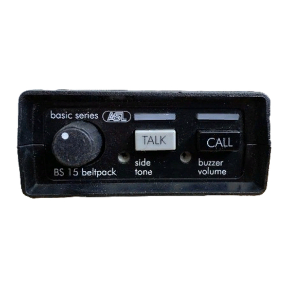
FRONT PANEL CONTROLS
1
VOLUME control knob
This knob adjusts the listen level for the headset.
2
TALK button
This push button activates the headset
microphone, the large green LED indicates if the
microphone is switched on.
3
CALL button
This push button activates the call system. By a
momentary push a call signal is sent to all
stations connected to the intercom channel and
the call LED's start flashing. Push and hold the
CALL button for 2 seconds activates the call
buzzer. After the CALL button is released the
LED's l continue to flash for a further 2 seconds.
6.0
REAR PANEL CONNECTORS
6
LINE connectors
These XLR-3 connectors are for connecting the
BS 15 to the intercom system. The female
connector is for input. The male connector is for
extending the intercom line to other user stations
('daisy chaining').
PAGE 4
User Manual BS 15 / Issue 2011 © ASL Intercom BV
.
4
SIDETONE trimmer
This trimmer adjusts the level of your own voice
as you hear it in your headset.
Side tone adjustment procedure :
set trimmer in start position : fully
clockwise
switch off the microphone of all connected
(speaker) stations
switch on the microphone of the BS 15
turn up the volume
speak into the headset microphone
adjust the listen level by turning the
sidetone trimmer.
The operating area is between fully clockwise and
minimum level. Adjusting the sidetone does not
affect the level of your voice as it is heard by other
stations.
5
BUZZER VOLUME trimmer
This trimmer adjusts the volume of the internal
buzzer, which is located behind the front panel.
The buzzer is activated if you push the CALL
button of this BS 15 (or a CALL button of any
other station on the channel to which the BS 15 is
connected), longer than 2 seconds.
Line connector pin assignments:
pin 1: 0 V / ground shield
pin 2: +30 V power wire
pin 3: audio wire
7
HEADSET connector
An XLR-4 connector for the connection of the
local headset. The headset can must have a can
impedance of minimum 200 ohms, or each
minimum 400 ohms when there are two cans in
parallel. The mic may be of the dynamic or
electret type.
Pin assignments:
pin 1: Shield mic. (GND)
pin 2: mic. +
pin 3: phones +
pin 4: phones -