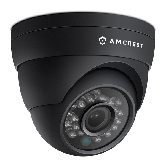
Amcrest AF-2MDT-28B Manuale d'uso - Pagina 5
Sfoglia online o scarica il pdf Manuale d'uso per Telecamera di sicurezza Amcrest AF-2MDT-28B. Amcrest AF-2MDT-28B 10.

Installation
1)
Locate the position in which you would like to place your camera and apply the included mounting sticker to
the mounting surface.
2)
Using a drill that is the same diameter, or slightly smaller than the included drywall mounting wall anchors,
drill out the smaller circles on the sticker and insert the drywall mounting wall anchors.
Note: The wall anchors should be in the same bag as the mounting screws and are designed to secure the screws
when mounting the camera.
3.
While holding the camera, unscrew the camera's base plate by turning it counterclockwise until the base plate
separates from the camera.
4.
While leaving the cabling to the camera still threaded through the base plate, match the holes in the base
plate to the holes of the wall anchors on the mounting surface. Then, using a Phillips head screwdriver, secure the
base plate using the mounting screws.
5) Pull the excess cabling through the cable routing channel and place the camera back onto the base plate by
turning it clockwise.
Tip: During this step you will be able to direct the camera framing to your liking. Compressing the camera "eye" to
the base plate will help secure the camera while keeping the desired field of view.
Connection
This camera series will have three leads at the end of the wiring harness. Their functions are as follows:
Green: TVI,CVI,AHD, and CVBS
Red: DC12V, 2.0A power input
Black (Dip switches): Please follow the diagram below for configuration settings:
Note: If the proper mode configuration is not set, you will not be able to view your camera on your DVR. Please
make sure you have the proper settings on your camera before you begin setting up or installing.
To connect your camera to your DVR, please follow the steps provided below:
Note: Make sure you have the proper mode configuration on your camera before running or connecting any
cables. Refer to the Figure 1-1 for more details on how to set mode configurations for your specific DVR.
Step 1: Connect a BNC (coaxial) cable to the video out connection of your camera.
Figure 1-1
5
